1/4" Trim Router Extension Shaft

Boy am I glad I posted this question, while still in the "thinking stage". Thanks to all for your concern for my safety. Well, my idea, although still pretty bad I guess, was not quite as bad as some of you thought. Allow me to at least partially redeam myself. I certianly wasn't going to use this as an "extended router", or even as a hand held " long nose die grinder". Sorry I didn't put this in the first post, but kd4gij nailed it, I was thinking of an inexpensive way to set up a quick "tool post grinder" to grind the jaws on a badly machined chinese 4 jaw that's not usable as is. I already have the little trim router, and aluminum plate for a sturdy mount to the compound, and come to think of it, somewhere I'm sure I have one of those "router speed controls" (if I can find it) that I could use to get the RPM's down. I could even re-evaluate the 4" length, and make it just long enough to reach in to the back of the chuck jaws, maybe 2 or 2 1/2" . Also, instead of the collet nut and collet on the end, I could do as Tony Wells did and just have a "concentric" "perfectly true" "reamed" hole with a set screw to hold a small grind stone with 1/4" shaft. Well, what do you all think now? Still a bad idea? Probably so, but even if this idea goes no further, I would still love to learn how you guys would make a shaft like I described in the OP, and have it run true (order of ops). Thanks again, for your safety concerns, and help. JR49
 
If you'd be going to that much bother, couldn't you just make a spindle, pair of "magneto bearings" in a suitable tube, pulley driven by your trim router (with a similar pulley held in the router collet) - the "Workshop Practice" book 27 - about spindles - would be a good place to look for designs/hints, there's an ID grinding spindle that "has to run above 10,000 RPM" in chapter 10 that takes Dremelloid accessories, looks inexpensive to make (carefully!)

Dave H. (the other one)
 
Another option (assuming I'm understanding your router). Rather than making a larger shaft with an internal thread that engages over the threaded arbor stub normally used for the tightening nut, you could just turn the shaft end to whatever largest size collet the router uses. For example my collet is 0.25", so imagine a 0.5" shaft turned down to 0.25" on the collet end for say 1" or whatever length. Tighten it using the existing nut. By comparison, if your nut was say 0.5" OD threads, your shaft would have to be ~0.75" diameter to accommodate ID threads & might not not run as concentric

On the business end, kind of depends on what you can find for grinding wheels. ID wheels like what are used on toolpost grinders are available. But they seem to be a bit more limited in terms of available grit/diameter/screw hole combos. Whereas those typical .250" shanked stones are dime a dozen. So on this end of the shaft you could drill a matching hole & set it in place with notch & setscrew. The shanks I have are not precision ground btw, typical offshore utility grade. Then you need a way to dress the stone once everything is set in position. I would go very easy on hardened jaws, have a controlled way measuring depth like a DTI. And protect everything from grit like paper shop dowels.
http://www.traverscanada.com/34group-a34-14-shanks/p/48012/
 
Peter, I think if JR is going to spin it at 25,000 RPM with a trim router, he can't risk anything being even slightly eccentric, at that kind of RPM it'll turn into a flail within a few milliseconds and try to kill him...

Dave H. (the other one)
 
Yup, I think you are exactly right. On my Makita mini router which I've re-purposed into a nifty edge chamfering beveller (pictures coming, still tweaking!) I have a vario rpm knob that goes from 8-24K unloaded. But I'm not 100% sure if that lower rpm equates to safer. My understanding is rpm comes from abrasive wheel SFM recommendation, so you would need a finer depth & traverse speed without stressing the stone? Or is it more a manufacturing efficiency thing? Anyway, my biggest concern would be the potential for runout effect (extension shaft, router bearings, fit-up, direct drive vibration...).

Just noticed this DIY spindle, but there are many like it on the net.
http://www.homemadetools.net/forum/tool-post-grinder-plans-46306#post66224

Personally for a 1-off jaw truing, a borrowed die grinder in a secured toolblock might be the best solution/
 
I like the metal pipe/tube holding bearings & ran by a flex shaft idea myself. Heck I think I'll even make one. With the grinding stone mounted to the contraposition use a diamond to true it up.

Just wondering if you have tried remounting the Chuck in different poisons or moving the jaws in the Chuck to try to get rid of the runout before grinding. My three jaw has quite a bit of run out but since I usually cut the outside & turn the center in the same setup it isn't a problem. If I have to pull a part I mark it where it lines up with the same jaw when putting it back. On the times nether of this are an option I use my 4 jaw chuck & align it with a indicator.
 
My three jaw has quite a bit of run out but since I usually cut the outside & turn the center in the same setup it isn't a problem

Thanks for responding, kingmt01, I'm actually talking about my 4 jaw, so runout isn't the problem. Its that the part of the jaws that make contact to grip the work are machined so poorly that they hold the work at an angle to the spindle axis. I'm pretty sure I can fix them once I figure out this tool post grinder thing. Oh, and also figure out how to hold a preload on the jaws. Happy Thanksgiving, JR49
 
Preloaded would be easy. Ether clamp something in the back of the jaws that will be cut away later or something that will be held by the outside of the jaws like a ring from a large pipe.

Twisting a wire to hold tension would probably even work.
 
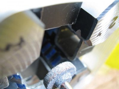
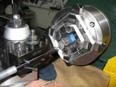
To preload the jaws on my 4 jaw, four pieces of 1'' square tubing were placed between adjacent jaws as shims and the jaws tightened inwards. The thickness of the shim determines the radius on the pads of the jaws. IMG_1107.JPG
IMG_1108.JPG
 
To preload the jaws on my 4 jaw, four pieces of 1'' square tubing were placed between adjacent jaws as shims and the jaws tightened inwards. The thickness of the shim determines the radius on the pads of the jaws.

Tozguy, I see in your pic that you simply used an air powered pencil grinder mounted in a tool holder. I have one like that and am going to give your set up a try. Is there anything I should know about your process that I'm not seeing in the pic?? Is that stone something special, or one that I would pick up at the hardware store?? Thanks for posting, and Happy Th--OOps, just noticed You are in Canada, So Happy Machining, JR49
 
Back
Top