Yes, Another G0704 Cnc Conversion

Sorry for the delay getting you the models, I was busy with work. Here is the link to the housing in Fusion 360, if you don't use Fusion 360 let me know and I'll get some drawings made up.

http://a360.co/2kM9dxF

Thanks.

I downloaded Fusion 360 and played with it a little, then had that computer barf on me before I got anywhere. I haven't installed it on the replacement computer. This will be a good excuse to re-download Fusion and do the tutorials.
 
Sorry for the delay getting you the models, I was busy with work. Here is the link to the housing in Fusion 360, if you don't use Fusion 360 let me know and I'll get some drawings made up.

http://a360.co/2kM9dxF

Hate to bug you, but I had originally considered microswitches for limit switches and read complaints about their accuracy. Do you have any data on what kind of position uncertainty there is with these? Do you just use it to keep from raising the z-axis too high, or what?


Bob
 
This optical switch in the enclosure I made is repeatable to <.001", I don't have a tenths indicator to measure anything less. With the optical switch as a home I have soft limits set in LinuxCNC to prevent the head raising too high. I didn't use micro switches because of the same accuracy concerns.
 
That might be it. The AC bearings are preloaded against the mounts, part of my upgrade plan is to preload them against each other and then capture the assembly. I'll make the y axis mount first and see how it performs, since that's the axis with backlash currently.

Sent from my Nexus 5X using Tapatalk

Why would you preload both the bearings against each other. I could be wrong, but I think that removes all the preload applied to the ball svrew, which is the main point of using two AC bearings. May as well use one standard ball bearing and tighten it down on that one bearing instead.
 
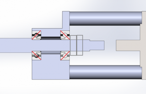
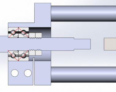
It doesn't due to the shoulder on the ballscrew. Here's a shot of the old vs new setup. The bearings were modeled wrong so the red lines are their orientation. On the old mount the through bore wasn't bored out enough so I used shims to only contact the outer bearing race against the mount. The shims aren't modeled.

Y_Old_Screenshot.PNG

Y_New_Screenshot.PNG
 
It doesn't due to the shoulder on the ballscrew. Here's a shot of the old vs new setup. The bearings were modeled wrong so the red lines are their orientation. On the old mount the through bore wasn't bored out enough so I used shims to only contact the outer bearing race against the mount. The shims aren't modeled.

Well, its hard to know where you are putting the shims in your new new model but in any orientation/configuration, you must have a gap between the two inner races at all times. If not, you are defeating the purpose of using two opposing AC bearings. Hope this helps.
 
Well, its hard to know where you are putting the shims in your new new model but in any orientation/configuration, you must have a gap between the two inner races at all times. If not, you are defeating the purpose of using two opposing AC bearings. Hope this helps.
Yea I get what you're saying, the actual AC bearings inner/outer races are offset, the ones in the model are just a generic ball bearing of similar dimension and don't show the offset. I've been using the setup for a while now and never updated the post, but currently I have no detectable backlash in my Y-axis. I need to make a similar mount for my X-axis.
 
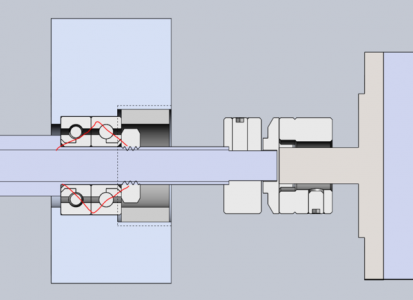
I remade the X axis, this is the concept:

upload_2017-3-27_9-12-47.png

I don't currently have a picture of it. I also used high end NSK bearings, noticeably better than the cheap AC bearings I got off VXB.

Current Backlash:

.0015 X
.0000 Y
.0005 Z

The last part I made was .015 over in X, any idea why? Just accumulated error in the ballscrew? I double checked the gibs using the indicator method.
 
Are you saying the part was .015 too big? Features were in the wrong place? Or is it that the part is distorted and maybe instead of a square it's more like a parallelogram, tilted from one Y extreme to the other?

I've had the experience where going back and forth over and over on an axis with a little backlash can lead to accumulated errors that get that big. Actually, quite a bit more than .015, but that was without backlash compensation being turned on.
 
The overall dimension is off by .015. I just enabled backlash compensation though and am getting 0 backlash on a dial indicator. I'm going to run the same part and compare the final dimensions. It's the housing for the optical switch, which I've made about 6 of just through troubleshooting the CAM. I measured and they're all within .002 of each other, albeit off by .015. So given that I've enabled backlash compensation I have high hopes.
 
Back
Top