- Joined
- Apr 27, 2014
- Messages
- 67
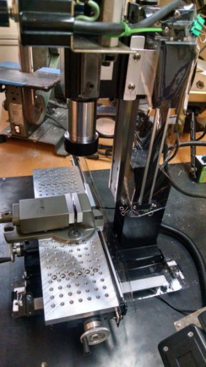
Well, I searched for threads specific to the X2 mill and couldn't seem to come with up many, so I thought I'd post this for others that may want to do the same.
First of all I purchased 3 iGauging units from an ebay vendor. There's a bunch of them. I got 2 ea of the 12" and 1 ea of the 6" units. I had to cut one of the 12" units down a bit for the X axis (used a dremel with a cut off wheel but you can use most anything and it doesn't damage the slider) but the others…(6" for Y axis and 12" For Z axis) went in without cutting down.
Here is the Z axis slide with the sending unit
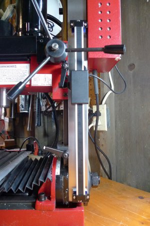
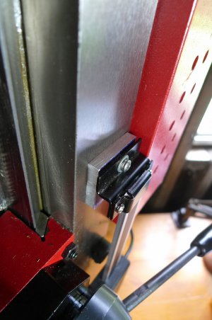
Here is a picture of the mount at the top of the Z axis slide. I had to raise the slide off the column with some 1/4" aluminum to allow the sending unit to clear the bolt that holds the counter weight on the other side of the mill. I also took the stock Z bracket that came with the iGauging unit and beat it flat, then made a much shallower Z bracket with a cut out that cleared the adjusting nuts for the column.
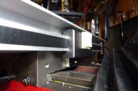
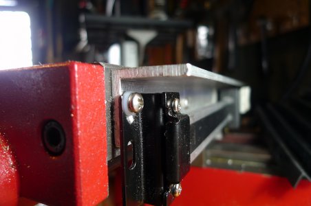
Here's a picture of the back side of the X table with the slide mounted. I first mounted 1x1 alum chip guard. The 6-32 screws pass through the bracket and the angle alum and only the X table is tapped. I already had the table off of the mill to work on smoothing out the ways and dovetails, so it was easy to put the table on the bench and mount the slide, but the sending unit has to be attached to the table and is stationary on the X axis so there was a lot of mounting and unmounting the x table in order to get the fit correct for the sending unit. Again, brackets were formed using the existing Z brackets and reducing the offset so that the spacing between the sending unit and the table was correct. I think if I did this again, I would leave the table intact and remove the column to allow access to the back of the X table. The other picture is of the end bracket of the X axis slide. I removed the bellows that covers the x axis leadscrew. I put some velcro on the back of the sending unit and on the bellows and when I use the mill will simply attach the bellows. The lip of the bellows tucks up under the angle aluminum chip protector quite nicely.
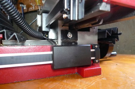
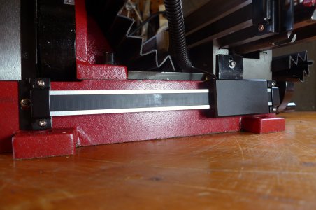
Here's a shot of the Y unit. Pretty straight forward here. The sending unit sits about 1/4" from the end of the X table so I again bent the Z bracket to fit. It's important that there is no stress or twisting on the slide so you have to fool around with it until it's right. This sending unit slides the length of the slide so you have to make sure it clears the feet of the mill.
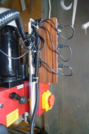
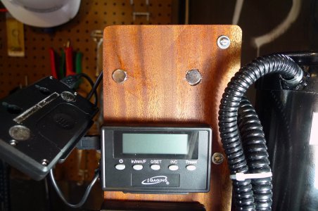
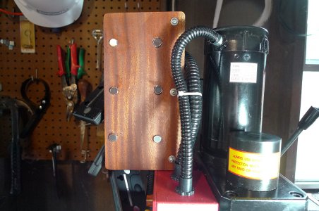
Now on to mounting the displays. I had some angle alum and some mahogany laying around. I also had some 3/8" magnets that matched the magnets on the back of the displays so I measured everything and then recessed the magnets into the wood using a forstner bit. The magnets sit above the surface of the wood about 1/8" and they click into the slight recess with the magnets on the display unit. They stay put but are easily removed to replace batteries when needed. The angle alum was mounted to the back of the main power switch using two 6-32 screws, washers and nuts. Plenty sturdy enough. I put some wire tie do dads in the back so I could get all the wires out of the way. Then I got some of that split plastic wire housing stuff at the local hardware store and ran a length of that from the X and Y sending units down to the machine.
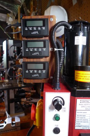
And here's what it looks like now
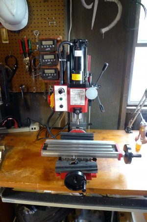
Now to make some chips
Steve


First of all I purchased 3 iGauging units from an ebay vendor. There's a bunch of them. I got 2 ea of the 12" and 1 ea of the 6" units. I had to cut one of the 12" units down a bit for the X axis (used a dremel with a cut off wheel but you can use most anything and it doesn't damage the slider) but the others…(6" for Y axis and 12" For Z axis) went in without cutting down.
Here is the Z axis slide with the sending unit

Here is a picture of the mount at the top of the Z axis slide. I had to raise the slide off the column with some 1/4" aluminum to allow the sending unit to clear the bolt that holds the counter weight on the other side of the mill. I also took the stock Z bracket that came with the iGauging unit and beat it flat, then made a much shallower Z bracket with a cut out that cleared the adjusting nuts for the column.

Here's a picture of the back side of the X table with the slide mounted. I first mounted 1x1 alum chip guard. The 6-32 screws pass through the bracket and the angle alum and only the X table is tapped. I already had the table off of the mill to work on smoothing out the ways and dovetails, so it was easy to put the table on the bench and mount the slide, but the sending unit has to be attached to the table and is stationary on the X axis so there was a lot of mounting and unmounting the x table in order to get the fit correct for the sending unit. Again, brackets were formed using the existing Z brackets and reducing the offset so that the spacing between the sending unit and the table was correct. I think if I did this again, I would leave the table intact and remove the column to allow access to the back of the X table. The other picture is of the end bracket of the X axis slide. I removed the bellows that covers the x axis leadscrew. I put some velcro on the back of the sending unit and on the bellows and when I use the mill will simply attach the bellows. The lip of the bellows tucks up under the angle aluminum chip protector quite nicely.


Here's a shot of the Y unit. Pretty straight forward here. The sending unit sits about 1/4" from the end of the X table so I again bent the Z bracket to fit. It's important that there is no stress or twisting on the slide so you have to fool around with it until it's right. This sending unit slides the length of the slide so you have to make sure it clears the feet of the mill.


Now on to mounting the displays. I had some angle alum and some mahogany laying around. I also had some 3/8" magnets that matched the magnets on the back of the displays so I measured everything and then recessed the magnets into the wood using a forstner bit. The magnets sit above the surface of the wood about 1/8" and they click into the slight recess with the magnets on the display unit. They stay put but are easily removed to replace batteries when needed. The angle alum was mounted to the back of the main power switch using two 6-32 screws, washers and nuts. Plenty sturdy enough. I put some wire tie do dads in the back so I could get all the wires out of the way. Then I got some of that split plastic wire housing stuff at the local hardware store and ran a length of that from the X and Y sending units down to the machine.


And here's what it looks like now

Now to make some chips
Steve


Last edited:

