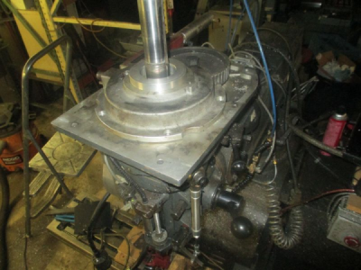
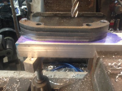
Here is another example of work holding and order of operation in the lathe. I am building a new bearing retainer for the spindle drive system in my mill.
http://www.hobby-machinist.com/threads/mill-spindle-direct-drive-conversion.49130/
This started out life as a 4x4x1 chunk of 6061 T6.
I didn't get any pictures of the work in the 4-jaw, but I center punched a divot in the center of the piece, and then just aligned that to the tailstock center. All of the internal work and face was done in one setup so the bores and face would be concentric and parallel.
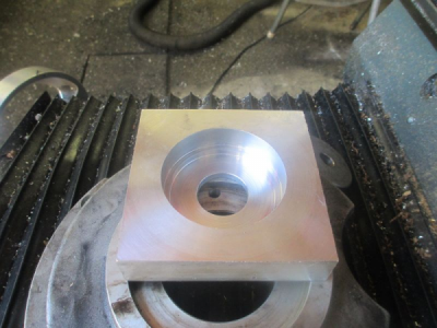
Then I grabbed a chunk of 2 inch shafting, and made a stub arbor to mount the part on to turn the OD. The snout is a press fit into the mating bore in the part. This insures that the OD is concentric to the ID. In this case, this sets the alignment of the bearing in the machine. Note the relief just larger than the locating diameter. I wanted the part to grab on the outer 1/4 inch or so of the stub.
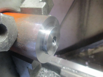
And the part mounted up
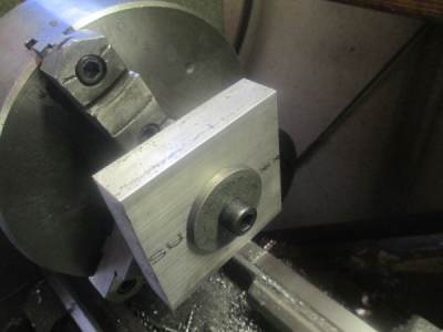
I didn't want the part to touch the jaws, so I left about a 0.030 gap when bolted up tight.
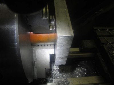
This should dispel some of the myth of interrupted cuts and carbide. I'm taking about 0.125 off of the diameter per pass at 460 RPM
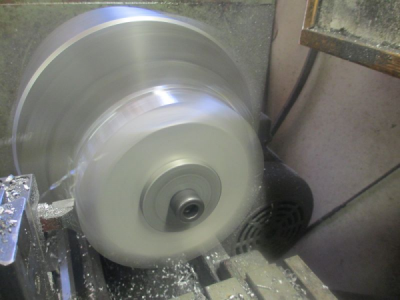
Once it's on size, then reverse the jaws and face off the excess material on the other face.
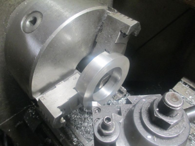
And there it is in place. Still need to drill & tap the bolt holes.
