- Joined
- Feb 8, 2014
- Messages
- 11,176
Thanks! Yeah any more pictures or videos would be great. Here are some questions:
1. Is it possible for the draw bar to get cross threaded?
Possible? Yes, but not likely. The biggest problem is thread wear over time.
2. If the spindle is not indexed then how do the drive dogs get aligned?
They don't, there are no dogs on the spindle on this machine. Just friction on the taper holds the tool holder, not really a great system for a 5HP machine.
3. What kind of tooling is that?
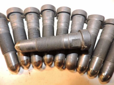
It is BT40, 5/8-11 thread. BT30 is a 1/2-13 thread.
4. Is the drawbar captive? This ties in with question #1 a bit. I've been thinking a captive drawbar would be best, so it would positively "eject" the tool. However when inserting a new tool, it would be best if the drawbar were "floating" so the ATC inserts the tool fully in the taper, ensuring alignment before the drawbar starts spinning, to prevent cross threading.
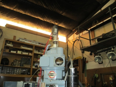
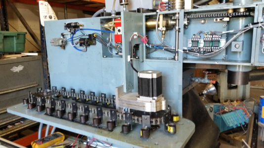
It is sort of captative, the free travel is limited by the impact wrench assembly. There is an impact socket on the impact wrench that engages the hex on the draw bar as I recall. The impact assembly is moved up/down by a pancake air cylinder attached to the belt housing. I think the travel of that cylinder is limited by the top of the drawbar and the socket depth. I know the drawbar is pushed down by the pancake cylinder. I can't exactly remember how it all goes together. I'll have to look, and get some pictures of it.
5. You mention an air brake but I saw the spindle turn a bit at the end of the video. Is it a weak airbrake? How much resistance is needed for the impact to do its job?
It doesn't require a lot of brake, and in fact maybe doesn't even need the brake to make it work. I'm pretty sure you could hold it with your hand, but not recommended. I think the timing is a bit off in the program, releasing the brake before the end of the impact cycle. That video was the first testing of the system.
6. Details (pictures, video, explanation, or some combo thereof) of how the impact interfaces with the drawbar would be appreciated.
This is the only picture I have of it right now, I'll get a few more with some detail.

7. What's the diameter of the drawbar? The bore of my spline is 1/2", think that's sufficient?
5/8'' in this case, in your case you would use a 1/2''
8. Have you ever had any issues with it? What kind? Do you like it? Think it's as good as a pullstud setup or TTS? Why/why not? Do you have any insight on why this isn't more common?
This thing has only been operated a few dozen times in my shop, just for testing, it has never done a tool change when doing actual work. This machine is not in use, it's only made chips a couple of times.
IMHO a tool changer on a knee mill is useless, at least unless you have a servo knee to drop the table out of the way to do the tool change. You only have 5 inches of quill travel, so not a heck of a lot of room. There is a reason that VMCs have 18 or more inches of Z travel.


