Vise Jaw lift, is there an adjustment on PM vises?

WobblyHand

H-M Supporter - Diamond Member
H-M Lifetime Diamond Member
Joined
Dec 18, 2019
Messages
7,320
My middling vise, SKU: VISE-4in-HIGHPREC seems to have more jaw lift than I'd like. Is there any adjustment that could be made to reduce the lift? When I purchased my PM25 last year, PM's best vise was either out of stock, or back ordered.

I do have a 3" toolmaker's vise, which I like a lot. The lift is significantly less than the vise above. But it's more limited in things I can clamp. Is there anything that came be done to "fix" the 4 inch vise? Or should I just use it as a general purpose vise in the garage, and get a better one?
 
Looks like it's just another Kurt clone that get branded all sorts. It should be like this inside:


So a quick machining job should sort your issues, all other things being equal.
 
So that looks a lot like the junker-ebay vise that I got (and cleaned up for my shaper, see my history for the project), I'm guessing their definition of 'high precision' is different than mine :)

That is a ang-loc style vise (like the Kurts, which uses a 1/2 ball on a 45 degree angle inside the jaw to prevent jaw lift (though, it is often still POSSIBLE, but the action of clamping should force it downward).

There are two different things you can do to help out here:

Remove the jaw, there is a single set-screw in the back-center of the vise. If you loosen it, the jaw itself should lift forward and straight up. The first way to help with jaw lift is to adjust that set-screw. It should be tight enough to allow the jaw to not pull off, but not so tight as to prevent the jaw from moving up/down.

The second is straight polishing :) There are a few surfaces you want to make sure are smooth and greased.
1- The spot that the set-screw hits on the back of the nut. If the set screw catches there, it can do some odd things. This is often a raw-casting on the cheaper vises.

2- If you reach up inside the jaw (or it just fell out), you can find the 1/2 sphere. On Kurts, this is a precision ground part. On the cheaper vises, this is a raw casting. You want this to be as smooth as possible. Also, you want the side inside the jaw (the 1/2 circle) to be smooth and without burrs, but that is harder to get to. In my case, I was able to hit it with a carbide burr and get it more or less smooth, then covered it in grease.

3- Make sure the part of the nut that interfaces with the ball is smooth. You want the act of tightening the vise to force this 45 degree 'wedge' 'up' so that it pulls the jaw down. On mine, this was a super rough casting, and didn't slide on the 1/2 sphere at all.
 
@ErichKeane, I didn't fully follow your description, since I haven't opened it up yet. But now I have an idea what to look for.

@Lo-Fi, wow, quite a loquacious fellow! It was only after he started putting things back together, that I started to understand what he was doing.

Thanks for the ideas.
 
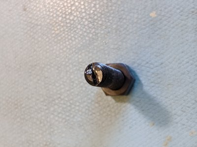
Ok. Took it apart. First thing I found out was the set screw wasn't tight! It was very loose. While adjusting it, I managed to jam it too tight, oops. Screw wouldn't move, Main lead screw was now too tight! Electrician's screw driver with hardened tip didn't fit right. Ended up machining a Chapman screwdriver bit down in diameter just enough for the bit to fit. (Hollow ground tip.) Then with the little Chapman ratchet, I was able to remove the screw. The set screw had fractured at the top edge of the slot - I was lucky to get it out. It is an 8 x 1.25mm screw 35mm long made from low grade steel. I'll replace it with a decent set screw. While literally screwing around with it a bit I measured the lift, hmm, it's a little better when it's not loose!

Yes, it can use some polishing alright. The surface the set screw hits, the bottom of the set screw, the ramp and the mate to the ramp are all pretty rough. I will have to get some pictures. There is no ball. There is some sort of weird piece of flat metal pushed into a hole? That metal isn't flat, and appears to have raised lettering on it! I wasn't expecting a lot but this is disappointing.

The good thing is 1) I have another vise to fix this one, 2) @Low-Fi has posted the video above so I have an idea how to fix it and 3) maybe I can make this one a little better. Can't be a lot worse than it is now...

Some pictures a little later...
I look forward to the pictures... The joint between the 45 angle on the nut and the inside of the jaw is supposed to have a half sphere, if it doesnt, I wonder if that is the problem!
 
Actually... I guess it isn't necessary that there be a half ball, if the two surfaces could slide, it would probably be ok. That said, on mine I also found that there was a part of the casting on top of the nut that kept it from staying down all the way, which caused some lift. I managed to machine a bit off the top to help. That said, I had machines/ground the bed, so I blamed that.
 
Well maybe it is a half sphere? Which side touches the ramp? The flat?
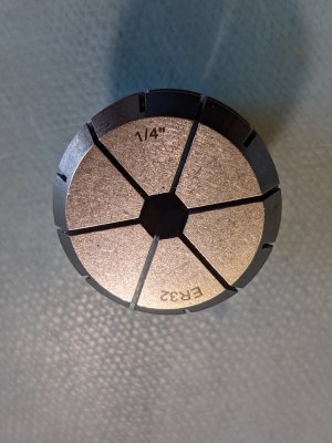
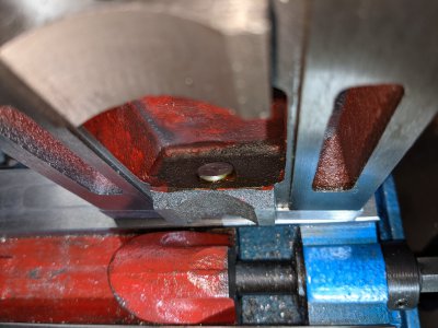
Some pictures... The new collet I used to machine the hexagonal bits. The set screw which fractured at the tip.
PXL_20210409_203626395.jpgPXL_20210409_203641103.jpgPXL_20210409_203202822.jpgPXL_20210409_203151740.jpgPXL_20210409_203234607.jpgPXL_20210409_203334074.jpg
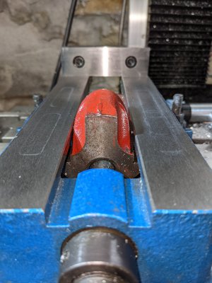
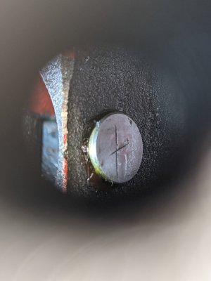
You can see the X on the surface of the half sphere? Reject? Why would someone do that? Can I just take it out and polish it on a diamond stone? I took the last picture through the set screw hole...
 
Yep, that is the 1/2 sphere! No idea why someone would put an X on it, but you can polish it up on whatever you have handy, and grease it up so it slides nicely. You also want it to pivot smoothly, so polishing the other side is a good idea as well. The ball is just kept in there by grease, so it'll pop out easy. The 'flat' touches the 45 spot on the nut, the other side is round so it 'pivots' inside the jaw a little.

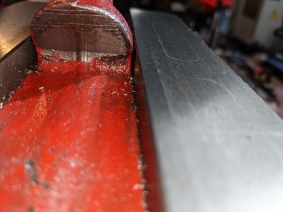
You can also polish the inside of the nut (picture 4!) to make it slide easier. It looks like someone started on that, but forgot to finish! If that ball gets caught on that machined bits, it'll cause jaw-lift.
 
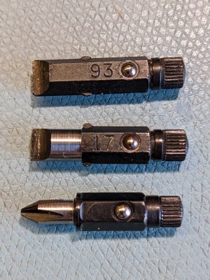
Picture of some of the Chapman screwdriver bits. Top one is unaltered. Middle one I did today to take out the set screw. Reduced the diameter to 7mm to fit inside the 8mm screw hole. Bottom one is a JIS#1 bit I did. It fits the screws in my laptop perfectly! Replacement bits are all under $3.
PXL_20210409_210057755.jpg
 
Back
Top