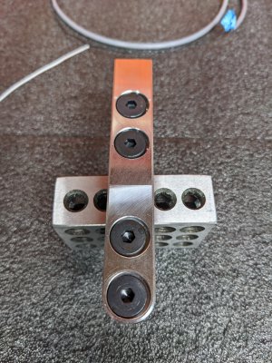
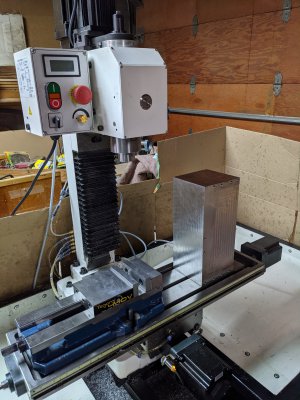
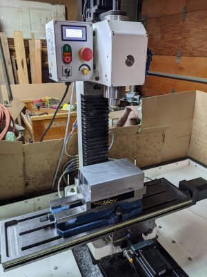
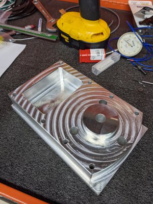
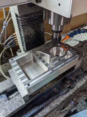
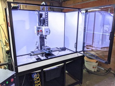
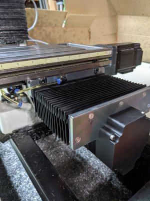
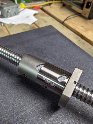
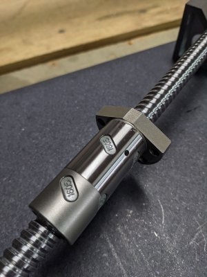
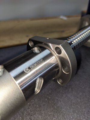
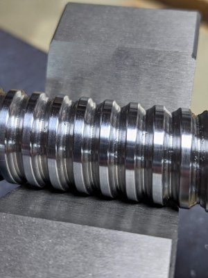
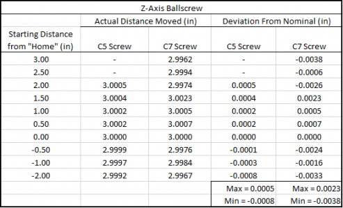
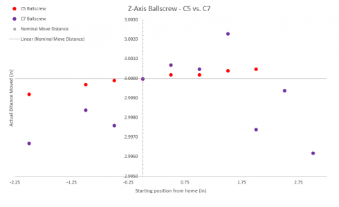
The X-axis has 2 angular contact bearings back to back on the left side of the table which provides all the axial support for the ball screw. The motor is mounted on the right with a small needle-bearing support. The needle bearing provides radial support and prevents screw whipping - this was actually an afterthought, but provides a lot more support to the ballscrew. Both the bearing mount on the left side and the motor mount on the right side utilize the locating pin holes that come factory with the PM25. The factory pins are 6mm OD - these holes were drilled larger and tapped for M8 bolts. The spacing of the factory M8 mounting holes were too narrow to utilize. The X-axis has 18.75" of travel.
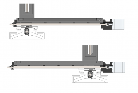
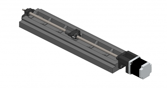
X-axis bearing, motor, and ball screw mount:
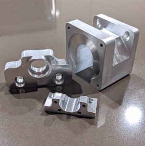
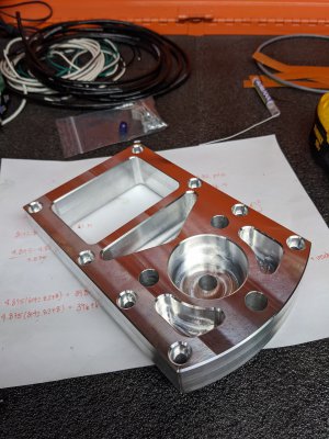
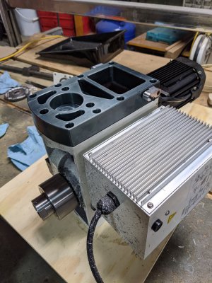
I decided to bead blast the X and Y-axis mounting parts before anodizing. They turned out looking pretty good. Someone with a keen eye will notice that the bearings in the following two pictures are actually installed the wrong way Don't make this mistake or you'll have a bad time...
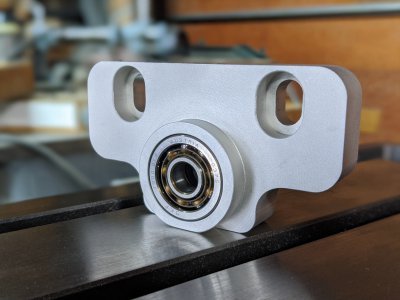
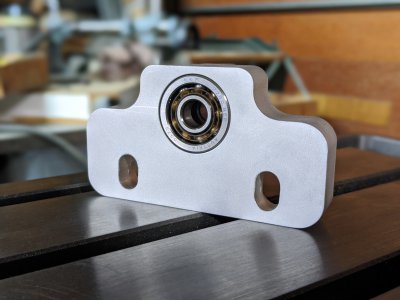
Here is the X-axis bearing mount:
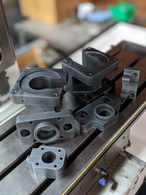
All the X and Y-axis parts:
Installing the X-axis ball screw:
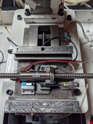
X and Y-axis motors and ballscrews installed:
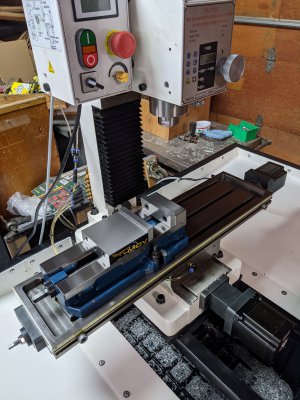
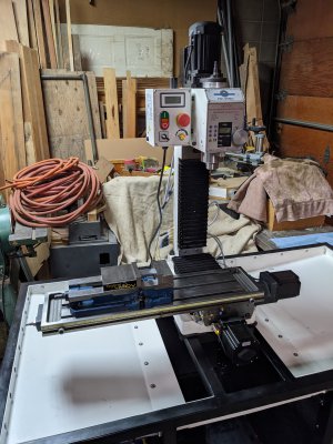
Here is the machine in its home position (positive travel limits):
-Adam.


X-axis bearing, motor, and ball screw mount:

I decided to bead blast the X and Y-axis mounting parts before anodizing. They turned out looking pretty good. Someone with a keen eye will notice that the bearings in the following two pictures are actually installed the wrong way
Here is the X-axis bearing mount:


All the X and Y-axis parts:

Installing the X-axis ball screw:

X and Y-axis motors and ballscrews installed:

Here is the machine in its home position (positive travel limits):

-Adam.

