[Mill] VF-25MV Build Thread

tkalxx

Registered
Registered
Joined
Dec 4, 2019
Messages
65
Hi all,

My name is Adam - a (soon to be graduated) mechanical engineer who got sucked into the hobby of building a CNC mill. I started a PM-25MV conversion roughly a year ago and I am the definition of a long-time forum lurker. I have spent hours upon hours reading and researching through forums without ever giving much feedback or response so I've decided to change that. I've always wanted to make a build thread to document my progress and hopefully be a resource for people who want to do their own conversion. Although they definitely don't know me, I wanted to give a shoutout to @macardoso, @shooter123456 and @ChrisAttebery. I remember even before I purchased my mill I spent hours studying their build threads and various pictures to formulate my own plan on how to go about converting my machine. Hopefully, I can add to the repository of pm25/g0704 mill conversions out there.

At this point in time, my mill is fully functioning and I couldn't be happier with it (although I will always find upgrades to do). I have a ton of pictures saved and thus I expect this thread to be very picture focused. Throughout my conversion, I have changed up components that I didn't like/had bad luck with and I hope to show my mistakes.

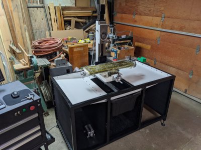
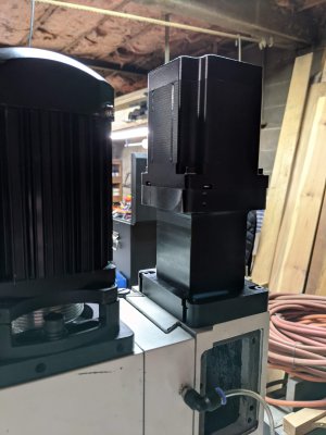
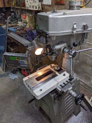
Here is a sneak peek at what I'll be building this thread up to +more as my mill continues to evolve:
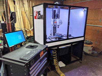
PXL_20210207_205932324.jpg

Some current specs at the time of writing this:
  • 906oz NEMA34 stepper motors on X and Y
  • 1200oz NEMA34 stepper motor on Z
  • 1605 OFU ballscrews on X and Y with 2005 OFU ballscrew on Z (C5 ground with 5% preload)
  • Pokeys57CNC motion controller running Mach4
  • 2.2kW BLDC motor with a custom 2 speed belt drive
  • Pneumatic power drawbar
  • Homebuilt mist coolant

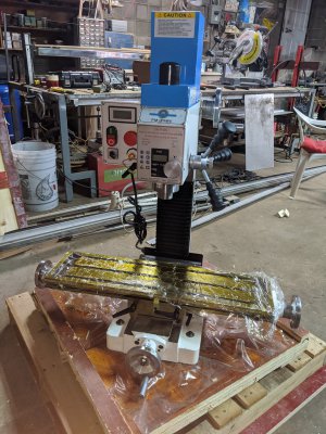
Like many, I started with a brand new PM25MV and quickly went to work disassembling and noting down dimensions. I chose a PM over the G0704 for one main reason: the spindle belt drive. I read on numerous occasions that the quality control of the PM variant was slightly superior to the Grizzly, but with time, I have come to realize that probably isn't true (for the money, they are both great machines).

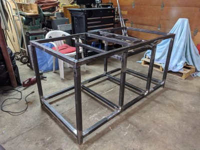
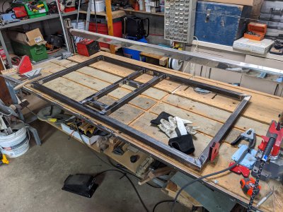
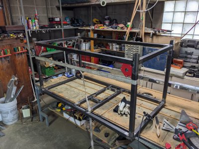
I began designing and building the stand that my mill would permanently live on. I always envisioned a full enclosure with hopes to implement flood coolant in the future and I wanted direct access to the Y ballscrew from underneath the mill and so the table reflects that. While building the stand I began designing all the motor and ballscrew mounts.
IMG_20200805_224045.jpg


The stand is made from 1.5"x1.5" HSS tubing. It's definitely overkill since it probably weighs close to 150-200lbs, but psychologically it makes the mill feel more rigid and sturdy.
IMG_20200815_131819.jpg


IMG_20200815_180212.jpg


IMG_20200816_225930.jpg

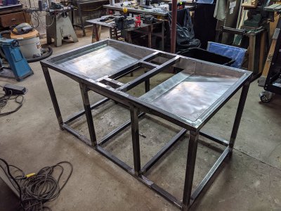
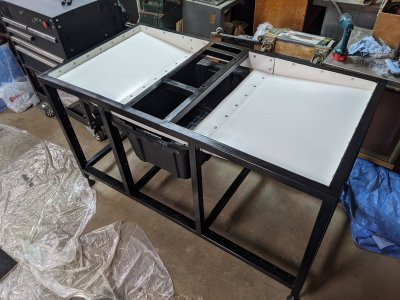
The chip trays are all sloped towards the middle of the table. Some angle iron was added to the large opening so that I could easily slide in/out a large container that catches all the chips.
IMG_20200818_221802.jpg


IMG_20200907_150803.jpg


IMG_20200907_194429.jpg
 
Last edited:
I would normally welcome you to the forum, but I'll just welcome you as a contributor. Looks like a great build and looking forward to seeing all the details.
 
Awesome looking machine, you are making me insanely jealous of the enclosure for sure. Might need to bug you for the plans :D

Welcome to the dark (contributing) side for the forum. Honestly this place is awesome and people are very friendly. Looking forward to following this as you post more.

PS: the Haas logo on the side cracked me up.

-Mike
 
Thanks guys, I appreciate the warm welcome. I have always found this forum to be very friendly and inviting compared to others.

One of the main attractions to converting a CNC was the fact that I could design and machine everything myself. Likewise, I have CAD models and drawings of absolutely everything on my mill. I know many people sell plans and complete kits (and I completely respect that), but with the variation in castings and variables in terms of ballscrew lengths, end machining, nut size, etc, I never had intentions of doing this. I am however willing to share plans and drawings as a reference for those who want them.

PS: the Haas logo on the side cracked me up.
The Haas logo has been the single best upgrade to the machine! lol

More to come soon,
-Adam.
 
Well, I for one would love a copy of the CAD, drawings, BOM, etc. for the enclosure.

I also have a bunch of 3D models for various elements on my G0704 that I have built and would be happy to share those as well!
 
I can definitely get a copy over to you. I'll send you a PM within the next couple days. :encourage:

-Adam.
 
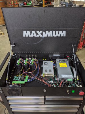
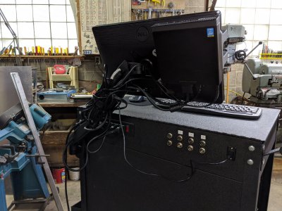
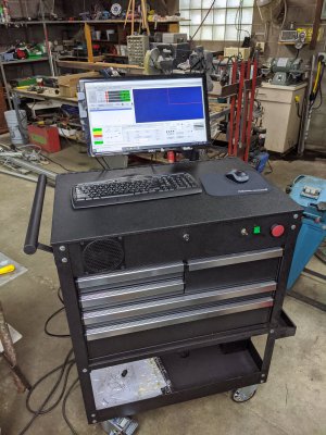
Moving along, at this point in time most of the critical electronics had been delivered. I had an old mechanics tool cart laying around in the shop that wasn't getting used and so I decided to convert the flip-up top section into an electrical cabinet. The drawers below would be used for tool and fixture storage.

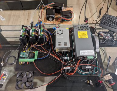
Unfortunately, throughout my mechanical degree I didn't learn much in terms of electrical and software. The extend of my knowledge I had from school was V=IR... That being said, I wasn't very confident building the electronics side of things and so I decided to temporarily mount everything on a scrap piece of MDF that was trimmed to fit in my mechanics tool cart and use it to verify that things were working correctly as I began prototyping and machining the motor and ballscrew mounts.

I started out very simple with a PMDX-424 motion controller, Mach4, three KL-8060E stepper drives, three 906oz NEMA34 stepper motors, a few proximity limit switches, a 48V switching power supply to power the drivers, and an auxiliary 12V power supply that I had laying around in my shop. I used whatever electrical wire I could find and started to wire everything up. I intended to use this setup purely for prototyping purposes so that I could jog/move each axis around and verify that the mechanical aspect of the build was solid.

IMG_20200804_072442.jpg


IMG_20200807_163806.jpg

I mounted a monitor arm to the tool cart that also doubled as a mount for the computer and prematurely drilled some holes to wire up M16 aviation plugs for the motors and proximity switches. In retrospect, I really wish I held off on installing the aviation plugs but at the time I guess I was super eager to see things taking shape and now I'm stuck with them due to the hole locations. If I were to do it again I'd pick up some PT series Amphenol mil-spec connectors or even the "low-grade" plastic LEMO's. There's something so satisfying about high-quality electrical connectors and to me personally, it's worth the extra cost - oh well, the cheapo amazon aviation plugs will do.

IMG_20200807_164831.jpg


IMG_20200807_163724.jpg

-Adam.
 
Last edited:
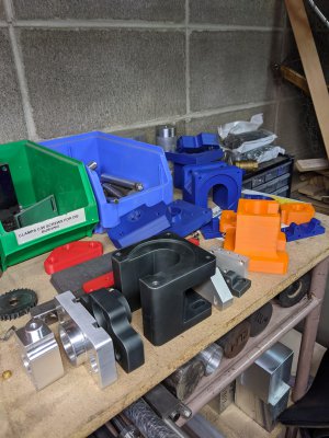
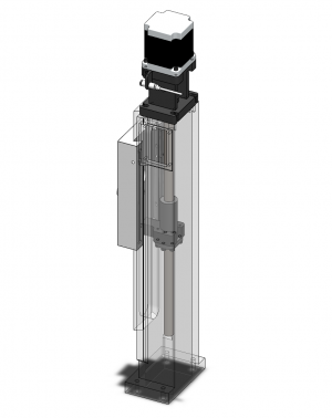
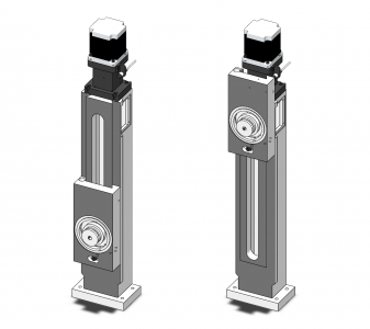
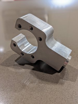
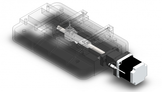
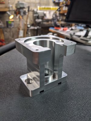
The first axis I started with was Z. My goals throughout the design of all the motor and ballscrew mounts was to create something that I was capable of machining on my manual mill/lathe, a package that was as compact as possible, as shielded as possible from the elements and something that achieved maximum possible travels. A big reason for choosing NEMA34 stepper motors on all 3 axes was due to the length of the motors - I did not like how long a comparable oz-in NEMA23 motor was. In addition, I wanted to future proof the design and knew that in the future if I wanted to upgrade to servos, finding NEMA34 servo frames would be easier than NEMA23.

I've decided I am going to append all my drawings in these posts as I move forward. I know many people may not be able to directly use them, however, you may be able to infer some critical dimensions if you are looking to make your own motor/ballscrew mounts. In addition, I will also append my ballscrew drawings. The ballscrew drawings are from when I ordered my C5 screws, however, they are identical in terms of end machining to the rolled screws that I started with. The rolled screws that I started with came from multiple vendors as I tried to source the cheapest option (one of which being Chai on Ebay). There is nothing inherently wrong with the C7 screws that I started with, but I wanted to pursue something of greater quality and that will definitely be a later discussion.

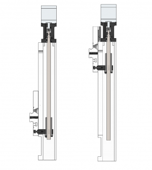
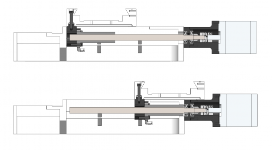
The Z-axis has 12.5" of travel.
model1.png
The bearing mount houses 2 angular contact bearings. I purchased SKF angular contact bearings and thus they are not a "matched pair". Because they are not a matched pair, you may be able to see the "air gap" between the inner races of the bearings. This allows proper preload for zero-backlash in the bearings. As for shaft couplings, I used clamping high-parallel misalignment couplings available from McMaster. The couplings have been great and I have had zero issues with them.

limits1.png
limits2.png
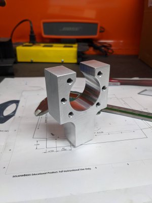
Z-axis ballscrew mount.
IMG_20200820_223622.jpg

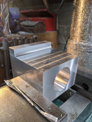
Since I have a lathe, I decided to bore all the large holes, including the bearing bores, on the lathe. This isn't necessary as it's entirely doable with a boring head, however, the lathe makes quick work of it.

IMG_20200829_121516.jpg


00100trPORTRAIT_00100_BURST20200829181532419_COVER.jpg


00100lrPORTRAIT_00100_BURST20200825225332988_COVER.jpg

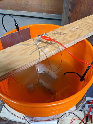
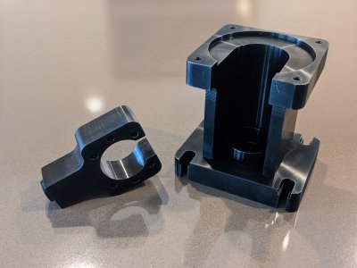
At the time, I was very invested in experimenting with anodizing. The motor/ballscrew mounts seemed like a great way to practice and begin solidifying my anodizing process (side note: I still haven't figured out a good process, my anodizing is very hit or miss). The large majority of the machined components for my conversion were anodizing black.

PXL_20201007_004251767.jpg


00100trPORTRAIT_00100_BURST20200830150659351_COVER.jpg


PXL_20201007_004603142.jpg

-Adam.
 

Attachments

  • ZA014.PDF
    300 KB · Views: 14
  • ZA016.PDF
    247 KB · Views: 15
  • ZA017.PDF
    283.3 KB · Views: 13
  • ZAS003 - rev03.PDF
    95.7 KB · Views: 16
Last edited:
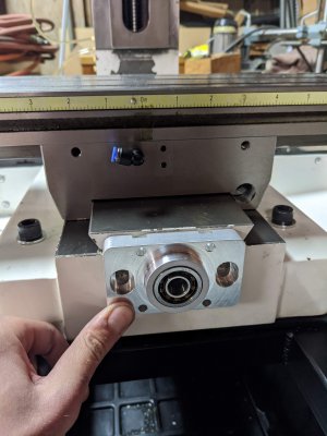
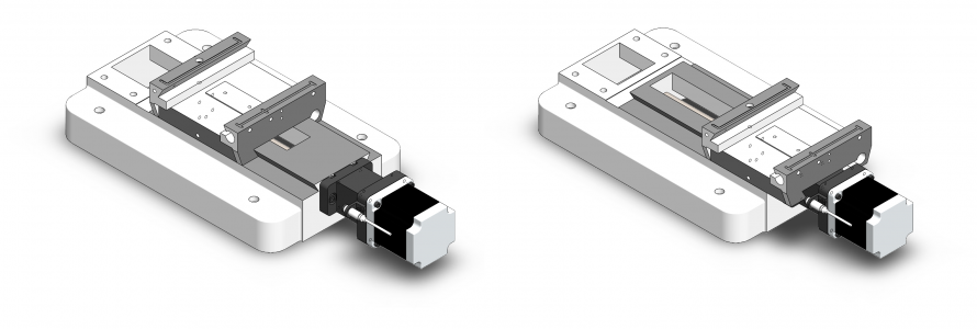
The Y-axis was next and proved to be a little more challenging simply due to design goals I set out for myself. In order to achieve maximum travel, the ballnut mount was secured to the ballnut in an unconventional way. Initially I was concerned about the rigidity of this setup and had plans of machining a new mount once I had the CNC functioning, however, since the ballscrew is so short on the Y-axis, the ballnut mount proved to be no cause for concern. Mounting it in this fashion to a double ball nut gave me 7.5" of Y travel without more than 1/3 of the saddle overhanging the dovetails. Notice how the ballnut actually fits through the casting on the front of the mill for roughly an additional 3/8" of travel.

model1.png

limits1.png

limits2.png

After disassembling the table and saddle, I discovered the casting inconsistencies that everyone talks about with the PM25/G0704 variant mills.

PXL_20201018_012914264.jpg

Because the casting was not at all flat or perpendicular to the ways, this robbed me of some of my planned travel. I decided to put the base on my tiny round column mill and touch it up before installing everything.

PXL_20201018_012655322.jpg

After:

PXL_20201018_024436567.jpg

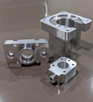
Collection of 3D printed prototype parts for fitment checks along with a few final revision machined components:

PXL_20201003_234039068 (1).jpg

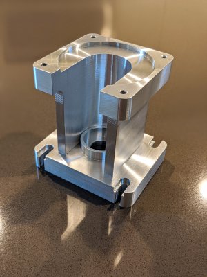
Y-Axis bearing mount. The bearing mount utilizes the original M8 tapped holes in the base casting:

PXL_20201005_013216866.jpg

Made a little oops and crashed my endmill into the motor mount on the final mill op. Luckily it's the bottom of the motor mount when installed so it's barely visible.

PXL_20201005_012714819.jpg

original_3d305c12-232d-4b12-9f8b-be5a2601d3d2_PXL_20201005_044558076.PORTRAIT-01.COVER.jpg

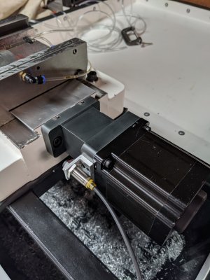
Y-axis ballscrew, bearings, motor and homing switch installed:

PXL_20201018_193554603.jpg


-Adam.
 

Attachments

  • YA009.pdf
    190.4 KB · Views: 11
  • YA010.pdf
    276.1 KB · Views: 10
  • YA011.pdf
    259.7 KB · Views: 10
  • YAS003 - rev02.pdf
    26.7 KB · Views: 10
Last edited:
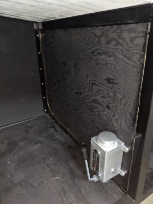
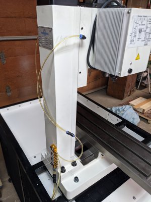
My oiling system uses a bridgeport style one-shot oiler that I bought cheap on Ebay. The oil pump has a 6mm OD compression fitting output that feeds from under the mill table up to a 6-way manifold mounted to the back of the column. The 6-way manifold was also an Ebay purchase and has a 6mm OD compression fitting input and 6 flow regulated 4mm OD compression fitting outputs.

PXL_20201003_213715128.jpg


PXL_20201003_213703281.jpg

The outputs from the 6-way manifold are all 4mm OD polyurethane tubing into push-to-connect fittings that supply oil to the ways and ballscrews. The PM25-MV comes factory with ball oilers for each axis. I drilled these out and replaced them with press-fit 6mm brass bushings that are M4 threaded on the ID to accept elbow push-to-connect fittings (see BA022 drawing attached for the bushings). I believe I stole this idea from a video that Franco made on youtube.

One of the flaws that I discovered with the PM25-MV is that although it comes factory with ball oilers, they provide absolutely no lubrication for the dovetails that mate with the gibs. If you were to squirt oil into the factory oil holes, no oil would make its way to the side of the gib that is in contact with the moving dovetail. In addition, the gibs are 'smooth' and have no oil channels to disperse the oil. To address this issue, I ended up drilling a small hole in each gib that was cocentric with the oil hole and additionally added some small grooves into the gib surface that mates with the moving dovetail with a 3/16" ballnose endmill. Unfortunately, I don't seem to have any images of this process.

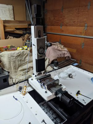
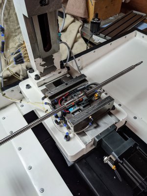
Of the 6 outputs from the 6-way manifold mounted on the rear of the column, 3 of them supply oil to ballscrews, and 3 supply oil to the ways. In order to achieve this in a somewhat decent package and to mitigate the risk of snagging or tangling oil lines, I made an additional manifold that mounts to the saddle of the mill.

PXL_20201017_235805287.jpg

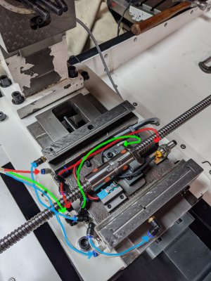
The outputs from the saddle-mounted manifold split oil supply to the X and Y dovetails along with the X ballscrew.

PXL_20201022_043349884.jpg

Here's a picture that hopefully makes things a little more clear as the underside of the table is a convoluted mess (although everything is very hidden once the table is installed). Red = Y-axis ways; Blue = X-axis ways; Green = X-axis ballnut

color_coded_oil_lines.jpg

The Z ways and ballscrew along with Y ballscrew get oil directly from the 6-way manifold routed behind the column of the mill.

Overall, the whole system works - all critical components get a healthy dose of oil. However, the system is not perfect. The "one-shot" oiler has turned into being a "two-pump" oiler simply due to backflow. There is an oil-compatible check valve installed between the bridgeport style pump and the 6-way manifold which does work and prevents backflow into the pump. I also have push-to-connect check valves installed for each individual line, however, I haven't been able to source oil compatible check valves for 4mm OD tubing. From what I can tell, backflow occurs in the Z axis lines due to gravity which forces standing oil in the lines back to the 6-way manifold and through X and Y lines. When I leave the machine for an extended period of time, the Z axis oil lines empty themselves and I am left with a thin layer of oil covering the base due to seepage from the X and Y dovetails. Because of this, it took a while to tune the flow regulators on the 6-way manifold, and now it has become a "two-pump oiler" in order to get the volume to fill the Z axis lines and reach the dovetails/ballscrew.

If anyone knows a source for some half-decent quality 4mm OD check valves, please let me know. I would love to try them out.

-Adam.
 

Attachments

  • BA022.pdf
    16.9 KB · Views: 10
Back
Top