Very slightly enlarging a hole?

Set screws are the spawn of Satan!

Joking aside, a set screw will mar that nicely polished shaft, leaving a burr that will hang up in your nicely fitted brass part. If you absolutely must use a setscrew, make sure to put a flat on the shaft so the burr will be kicked up on the flat and won't touch your brass. Better would be to split the brass part and using a clamping screw, or make a split cotter or something like that.
Totally and emphatically agree with you!
 
I agree too. That's why I bought some "non-marring" brass-tipped set screws, which are also have flat faces. If that's still too hard against steel, there are also plastic-faced set screws available.

I really don't want to machine a 12-18" flat on the rod. I am also reluctant to start down the road of split brass parts (if only because of my meager experience with machining).

The part needs to be physically symmetrical, with an on-center of mass, including being aerodynamically symmetrical (so no flat on the rod either), plus also easy to loosen, move very slightly, and re-tighten.
 
I would agree with others that you should start a project specific thread for your pendulum project. The metrology forum would be the appropriate forum. I believe that you can have all your pertinent threads moved by one of the moderators.

Regarding a non marring set screw, machine a small Delrin plug the goes in before the set screw. If you want to get really fancy, you can machine shoulder on the set screw and fit the plug to the screw but a simple plug will work.
 
A 36" long by 1/4" diameter steel rod supported horizontally from the ends will sag 0.050" just from its own weight. If cantilevered from only one end it will sag a half-inch. Of course, maybe you are mounting it vertically so its weight doesn't tend to bend it. Doesn't change the fact that a 36" by 1/4" rod is about as stiff as a well-cooked noodle.

What are you using this arrangement for? Does it have to be free to slide in service, or does it get positioned and then locked down? If the latter, I'd slit the block and use a screw to clamp it down. You could use the 0.251 reamer for a nice sliding fit, then lock it for zero slop.

It will be hung vertically. However, your point is well taken. Hung one way, it will have a ~1.5 lb weight on its far end. Hung the other way, it will have only <=4 oz of extra weight on its far end. I imagine it would stretch slightly more one way than the other.

For that matter, as it swings (it's a pendulum), it may also bend slightly at the extremities of the swing (though by a small amount since the swing will be kept to only a few degrees). So yes, I've been concerned that 1/4" is too wimpy. Indeed, I was originally planing on an even heavier bob, but after receiving the brass for that, I decided it was too much.

Anyway, the shaft is made of Invar, and getting a heavier shaft in that material is both expensive and difficult at the moment, so I'll take this version to its conclusion, and maybe make a heavier one after I gain more experience with it.

The sliding part will be positioned and repositioned repetitively until the period of the swing is identical when hung both ways, but then locked down semi-permanently. Kater found this to be a very difficult and time-consuming process.
 
Last edited:
How wide of an adjustment range? More than an inch? Was thinking of something like a micrometer head or a differential screw.
The adjustment range needs to be many inches, perhaps up to a foot or more, so a screw wouldn't work well.

However, there will be a small auxiliary weight somewhere in the middle of the rod for fine center of mass adjustments. Kater used a micrometer screw of some sort to adjust that. That weight is, for now, my "test" brass piece that I've been discussing. Not knowing how to make something better, I was planning on using one of those non-marring set screws on that as well, though.

I'd never heard of a "differential screw" before. Interesting!
 
It will be hung vertically. However, your point is well taken. Hung one way, it will have a ~1.5 lb weight on its far end. Hung the other way, it will have only <=4 oz of extra weight on its far end. I imagine it would stretch slightly more one way than the other.
Fortunately stretch is very different than bending. Your 1/4" diameter rod has an area of 0.049 square inches. With a 1.5 lb weight, the tensile stress is 30.6 psi. Invar seems to have a modulus of elasticity of about 21 million psi. So your 36" rod will stretch about 52 micro-inches with 1.5 lbs hanging from it.

For that matter, as it swings (it's a pendulum), it may also bend slightly at the extremities of the swing (though by a small amount since the swing will be kept to only a few degrees). So yes, I've been concerned that 1/4" is too wimpy. Indeed, I was originally planing on an even heavier bob, but after receiving the brass for that, I decided it was too much.

Anyway, the shaft is made of Invar, and getting a heavier shaft in that material is both expensive and difficult at the moment, so I'll take this version to its conclusion, and maybe make a heavier one after I gain more experience with it.

The sliding part will be positioned and repositioned repetitively until the period of the swing is identical when hung both ways, but then locked down semi-permanently. Kater found this to be a very difficult and time-consuming process.

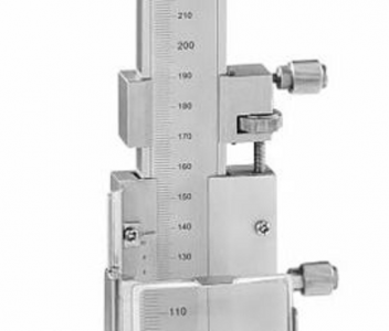
For the fine adjust, maybe you could copy the mechanism used on some vernier height gages and calipers. There are two slides connected by a fine pitch screw. The smaller slide can be locked with a setscrew, then you use the fine pitch screw to move the larger main slide. Finally you lock the main slide with another set screw. In the picture below, the main slide is at the bottom, the smaller slide on top. The adjusting screw is a length of fine-pitch threaded rod. It does not turn, it is locked into the main slide. The adjusting thumb-nut sits in a slot on the smaller slide, so as you rotate it the threaded rod and therefore the main slide are driven up and down.
1649702894288.png
 
For the fine adjust, maybe you could copy the mechanism used on some vernier height gages and calipers. There are two slides connected by a fine pitch screw. The smaller slide can be locked with a setscrew, then you use the fine pitch screw to move the larger main slide. Finally you lock the main slide with another set screw.
Yes, from the limited photos and drawings I've seen, that's what Kater used for the fine-adjustment weight. But his pendulum was perhaps 3 times larger and much, much heavier than mine, so he had more leeway to use such mechanisms. Mine is a miniature version for which the adjustment weight(s) are quite small by comparison.

In the end, it was demonstrated (by Bessel and Repsold) that excruciatingly-fine adjustments were not necessary if other methods and precautions were taken. My version is an amalgam of Kater's and Bessel/Repsold's. In the end, my version will be limited mostly by my (in-)ability to accurately measure the lengths involved.

By the way, I did actually mock-up a working version, but with 3-D printed parts instead of machined parts. It worked better than I expected, but the relative measurement crudeness (I only had a machinist's scale for the distance measurements), extra friction, etc., meant my measurement was just under 1% away from the best measure of local gravity that I could find for my general area. That's more than 2 orders of magnitude worse than Kater's measurement error, so there's a long way to go!
 
Fortunately stretch is very different than bending. Your 1/4" diameter rod has an area of 0.049 square inches. With a 1.5 lb weight, the tensile stress is 30.6 psi. Invar seems to have a modulus of elasticity of about 21 million psi. So your 36" rod will stretch about 52 micro-inches with 1.5 lbs hanging from it.
Awesome investigation!

As mentioned, the other problem I've wondered about is how the rod might bend during swinging. Bending is bad in at least two ways. First, it saps a tiny bit of energy with every swing via internal friction, and second, the suspended length and hence the period of the swing changes slightly as it swings. This is one reason why a "simple" pendulum - a heavy bob on a thin strong wire - proved inadequate, and people like Kater moved to compound pendulums with stiff, heavy rods. The latter wouldn't work either (compound pendulums are very far from ideal pendulums) until Kater re-invented the notion of a reversible pendulum.
 
The adjustment range needs to be many inches, perhaps up to a foot or more, so a screw wouldn't work well.

However, there will be a small auxiliary weight somewhere in the middle of the rod for fine center of mass adjustments. Kater used a micrometer screw of some sort to adjust that. That weight is, for now, my "test" brass piece that I've been discussing. Not knowing how to make something better, I was planning on using one of those non-marring set screws on that as well, though.

I'd never heard of a "differential screw" before. Interesting!
What kind of equipment do you have? Knowing that might make it easier to make suggestions. You really should have a centralized project thread!

For the many inch adjustment that doesn't need micrometer accuracy, I'd really just make some split collar devices. Especially since you now stated there is a third "fine tune" adjustment. A split collar can just be a thick washer, say 3/4" diameter, and a 1/4" thick, with a 1/4" hole through it. Or you can make the whole piece be split. You can turn and drill the washer on your lathe. For the slit, put the washer in a vise, and use a hacksaw to cut through one side. If you have a mill, use a slitting saw to make the cut. The "hard part" would be to drill and tap a screw. But you could file a flat for the drill to start. Would be ok in a drill press, or even easier with a mill. Here is a rough model. I just picked some odd values, but you could refine the idea. This would be for a 6-32 screw. with a counterbore for a socket head screw. Don't need to be this fancy.
splitcollar.jpg

I made a simple differential screw for tailstock adjustment. Came out pretty well. It has about 3/4" coarse adjustment and a much smaller fine adjust. What is nice about it is one turn adjusts at the difference between the thread pitches. This is something you could make on your lathe. I chose a 1mm pitch and a 0.75mm pitch. The differential screw adjusts 0.25mm per turn (0.0098"). In contrast, a 40 TPI thread would change 1/40" per turn or 0.025".
 
What equipment do I have? Not much. I have a Sherline 4400 long-bed lathe with some accessories like a 4 jaw chuck, a press, a portaband, some basic measurement tools (micrometer, etc.), plus a modest range of hand tools. It's apparently quite easy to spend thousands without feeling like you are making much progress on the tool front.

That off-center hole looks a bit iffy to drill on a lathe, and hack-sawing that slot would be nasty on a small part. However, I also just took delivery of a "cnc-ready" Sherline 5400 mill (my first reaction: Gasp! It's ... so tiny!). I bought it more to learn about CNC than to use as a working mill (I'm also currently building a control system for it), though I do expect it to do some small work for this and other small projects. I have modified it to work manually for now, but I haven't cut anything with it yet. Once it's up and running I can get a slitting saw and try to make a part like you drew in your last post, but I mostly think a simple set-screw would be OK too.

How does one make a project page? Anything special, or just start a thread?
 
Last edited:
Back
Top