Two Speed Reverse Single Winding Motor

Nick Hacking

H-M Supporter - Gold Member
H-M Supporter Gold Member
Joined
Jan 22, 2017
Messages
90
I hope I'm doing the right thing. I've drifted from asking about general wiring of the the whole machine to looking at the wiring inside my motor, so I've started a new thread....

The motor is three-phase, 415V.

The switch is a Kraus & Naimer A442 and a bit of digging on the internet showed me how it's wired. If I've understood it correctly, in position "1" the three live feeds go to the corners of the delta (T1, T2, T3).

In position "2" the three live feeds go to the middle of arms of the delta (T4, T5, T6) and the corners are shorted together so that the configuration is two Wye circuits, in parallel.

From this, am I correct in assuming that the motor will run from 240V (3 phase from a VFD) in position "2" - but with only about half the power - something akin to the performance of the motor running from 415V and the switch in position "1"?

I presume, if this is correct, that to get the machine to run at full tilt, I either need to find a 415V power source, have the motor rewound professionally, or fit a substitute motor?

Any advice, folks?

Kind wishes,

Nick
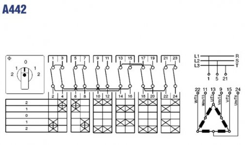
Kraus & Naimer A442.jpg

Kraus & Naimer A442.jpg
 
I will need to puzzle on thins some more when I get home tonight (a little rusty on my wye-delta transromations), but I think you should be able to wire it in the "2" configuration to the VFD and get full power, however, you will need a VFD that can supply 2x the full load Amps @415 V. The motor should give you the low speed rpm in this configuration. To get your full speed output, you could run the VFD @ 120Hz, since your mechanical setup should handle the increased speed.
 
Dear Henry,
Brilliant! I hadn't thought of driving it at 120 Hz. Thank you so much: you have given me hope.

Kind wishes,

Nick
 
Ok, I did some more research and here is what I figured out. In order to run at low speed and lower voltage, I think you would need to seperate the windings at T6,T4 and T5 and then reconnect them like the Low Voltage setup in the lower left corner of the picture. This is theoretical, and of course would require getting into the inside of the motor. Hope this helps
 
Last edited:
Thank you again, Henry.

At the moment I cannot get the wretched motor open. I need to remove the pulley stack to do that and (despite removing grub screws and circlip; and using heat) so far all I've managed to do is to damage the bottom pulley flange.

You don't think there's any mileage in the high frequency idea with a parallel Wye configuration? Given that it's a 2 HP motor, even a 25% inefficiency loss will still give me 1.5 HP at the business end. And, it's not as if the machine is going to be running flat-out all day. Overheating should not be too much of a problem.
Or am I clutching at straws?

Kind wishes,
Nick
 
Well, I could procrastinate forever but sometimes one simply has to get on and do.
After asking around, I've ordered a Mitsubishi 240V VFD. It goes up to something ridiculous like 400 Hz and is rated at 2.2 kW.
I shall put my mill back together, try it with the VFD and if it performs well enough, the trial is over. If it doesn't then the motor is going to have to come off again and I'll have to find some way into it to hack the internal wiring.
(Or take it to someone who knows what they're doing: but that's less fun.)

Either way, I shall report back in due course....

Kind wishes,
Nick
 
An update:

I cannot get the stacked pulley off the motor spindle for love nor money, but I managed to improvise a pair of jacks, using nuts and bolts, to pull the bottom plate off the motor, and the rotor, the motor spindle and the top bearing came out as one lump, leaving the windings in the stator in the motor housing. The shaft of the motor still goes through the plate and remains trapped by the pulley stack.

With the motor housing now upside-down, the wires all go in to the bottom of the housing which appears to be welded shut. There's a ring which (again) appears to be a permanent fixture, holding the stator and obscuring the view down the outside of the windings so I still cannot see which wires to cut and where to connect my new leads. Pulling this motor apart in a non-destructive way is proving to be a huge challenge. The angle grinder may have to come out, but I'm nervous about that because there's a real risk of turning the windings into scrap copper.

Meanwhile, my Mitsubishi VFD has arrived - it has a 500-odd page manual but, fortunately, has an easy-run mode for idiots.

There should be time for more experimentation at the weekend. I certainly think it's worth trying the high-frequency option before I imperil the integrity of the windings for ever. I can measure current output on the VFD and I have an optical tachometer to measure spindle speeds. I suppose that if I chart frequency, current and rpm, I'll be able to see when the current keeps increasing for no appreciable increase in speed, and that'll be the point where there's flux saturation, and so the maximum working frequency of the motor.

Thinking aloud, really, in the hope that someone will stop me if my idea sounds unutterably stupid....

Kind wishes,
Nick

[Edited after watching the induction motor 101 video, to correct my use of terminology]
 
Last edited:
Carrying on my one-sided conversation :)

I've discovered that my motor has an aluminium case. The stator is held in place by three allen-head screws and a very tight interference fit. I tried heating the case and cooling the stator, but I couldn't get it to budge, so I resorted to the angle grinder. The lid of the motor has four large solid lugs on the underside, in-between which are gaps for cooling. I cut through the lugs to take off the top and then carefully slit the side of the case. Apart from the case, I managed not to damage anything. The stator then came out and I've hacked the wiring as Henry suggested. Now I'm about to go back out to the workshop to try to put it all back together. I only have a DC TIG, and anyway, I've no experience of welding aluminium so there will be bodging, I'm afraid.

A quick question: with my AVO the DC resistance of each coil (there are six) appears to be of the order of 12 ohms. Does this sound about right?

Kind wishes,
Nick
 
Not sure if anyone is reading this, but if you are: SUCCESS!

Many thanks again to you, Henry, for pointing out what I needed to do.

At 50 Hz the motor draws about 6 amps under no load: roughly twice the rated current on the plate for operation in "series delta mode" at 420 V - so that seems about right.

Interestingly, it quite likes 70 Hz, and the no-load current drops down to 3 A at that frequency. However, at higher speeds it gets rather upset and intermittently stalls with currents reading 12 A or more and a lot of heat generated. It cannot be good for it to emulate a three-bar electric heater: I'll set the frequency limit to 70, I think.

Now for spindle speed tests and then I need to make the electrics permanent, set the mill up and start to learn how to use the beast. I've got a working Bridgeport and I'm as happy as a dog with two tails!

Kind wishes,
Nick
 
Just in case you all thought that I'd gone away....

Between skiing holidays and work, I haven't had a lot of time in the workshop recently, but I have managed to gather the electrical components that I need for my re-wire and low-voltage conversion. I found a rather dodgy Chinese "step up / step down" PSU on eBay for not very much. When I took it apart it is, as I suspected, an auto-transformer, but the 120 V it gives out from its centre tap works my cross-table feed with no difficulty. The motor is rated at 90 W and the transformer says it can handle 200 W, so even if the transformer's label is a little optimistic, it should still work. I've also bought a small 12 V DC PSU. I'm going to convert the 50 V work light to 12 V LED and the PSU will also serve for the control circuitry. All I need to do now is to wire it all together.

There's a second-hand machine dealer near here and I bought the biggest machine vice that I could afford from him. I've had the beast running and have actually done a little bit of milling and drilling. As YouTube's AvE says, a Bridgeport serves as a mighty solid drill press.

I have a 1J head and with the third pair of pulleys (marked 180 rpm in back-gear / 1,500 direct drive) I'm measuring 1,540 rpm at 50 Hz, which is gratifying. I've actually measured the spindle speed from 5 Hz to 120 Hz and with that pair of pulleys the spindle speed seems to be exactly half of the driving frequency. 5 Hz (ie 300 / min) gives a spindle speed of 150 rpm. 120 Hz gives a spindle speed of 3,600 rpm. In theory I should be able to run from 6.7 rpm (1st pair of pulleys, in back gear at 5 Hz) all the way up to 5,520 rpm (4th pair of pulleys, in direct drive at 120 Hz).

When I first rewired the motor, I found that it didn't seem to like going above 70 Hz - from the way that it started heating up and consuming current, I assumed that the motor was reaching saturation. Now that it's mounted on the machine in the correct orientation, it seems much more content. Maybe it simply didn't like lying on its side and running hot: in any event, the current it draws is only 1.5 A at 120 Hz so it seems to be happy enough the way that it's set up.

Once the rewiring is finished, my first project is to make a tramming device with a pair of clocks mounted in a block of aluminium. It dawns on me, however, that if I'm going to trust the tramming device, it has to be properly square, and so I'm going to have to tram the mill the old fashioned way first! After the tramming device, I'm going to have a go at making a quick-change tool post and some tool holders for my modified Myford/Drummond lathe. I'm quite chuffed at the moment: this month's Model Engineer has an article by Alan Hearsum, all about the way he built up my lathe from parts and modified the spindle. A sort of fame-by-proxy, if you will. I'm a dog with three tails now.

Kind wishes,

Nick
 
Back
Top