Trying to make sense of the threading charts

I think "better late than never" has chatter problems due to two issues.
First one is speed which can be rectified by either mechanically gearing down or changing the drive motor to dc or vsd control. Can be expensive but necessary.
Second issue is rigidity of crosslide and compound assemblies.
Are the gibs correctly adjusted?
How much compound slide overhang?
Cutting tool geometry may also rear its ugly head too.
 
Your interpretation is correct as far as I can tell. For a novice at threading, one must understand what threading actually is. I have a Grizzly G1550 which is almost identical to the Jet BD920, so I will present my thoughts from experience rather than theory. The lead screw is a 16 pitch, 16 TPI, screw. Therefore, if you want to cut a 16 TPI thread, the cutter must move 1/16 inch for one revolution of the spindle. The gear train is adjusted, gears changed as needed, to accomplish this as needed for the particular thread.

To cut metric threads, the gears are adjusted to move the lead screw in (sub)millimeters per revolution. This is accomplished by inserting a ratio of 127:120. The 127, a prime number, is the only conversion from imperial to metric. The 120 tooth gear could be a 100 tooth as well, although the 120 tooth allows divisions by 3. There are many gear combinations that yield "almost" metric threads, many to a factor of four decimal places. With the Modulus 1 gears, 25.4 DP, the 127 tooth gear is small enough to be usable.

When calculating the gearing required for a particular thread, the quick change (QC) box must be included in the calculations. As a starter project, the 127 tooth gear is removed, forming a spacer or buffer but not a portion of the reduction gears. Using a piece of plastic, 1/2 PVC is highly recommended, as a convenient material to practice. Set the machine up for 16 TPI and rotate the spindle by hand, watching the lead screw. The depth of cut is slight, just a few thousandths for each pass.

When cutting imperial threads (16 TPI, et al) the threading dial may be used. For cutting metric threads, the half nuts are never released. The machine is stopped, the cutter is backed out, and the machine reversed beyond the starting point. I do this for both imperial and metric simply because, as an old man, muscle memory for one process is easier to remember than two.

Once you are comfortable with cutting threads, imperial or metric, the range of small threads can be easily doubled on the down side, though not shown on the threading chart. Doubling on the upper side, coarser, is not recommended for such a small machine. The slowest speed, ~130 RPM, is a little too fast for threading close to the chuck. I built a 3:1 reducer that I will post in the archives, some day. But for the novice, it is simpler to rotate the chuck by hand. Twenty some years ago, there was a move on a board dedicated to these machines that advocated several methods for this, the most notable being a small steering wheel bolted to the spindle pulley.

Cutting Left Hand threads is also no big deal. The BD920 is not equiped to reverse the lead screw, although a tumbler reverse can be easily built. There are several iterations available on the Web. It is not an advanced project, but does require a little "finagling".

.
Bill is scary smart, articulate too.
For an old timer, you still got it!
 
My 'contraption' was built using the planetary gears from an automotive automatic(GM??). Essentially replacing the spindle pulley. . . It was posted for years on my web site, GoDaddy changed software a couple of years back and I am no longer able to (re)learn their system. I still have the PDF of the article and will one day post it to this site as an archive. Been waiting (hoping?) for an invite to do so. But mostly I'm not as 'functional' as I once was. The project was literally built from scrap, and most anyone with half a brain can eventually devise one once the seed is planted. Just takes a loonnngggg time.

Since I built the original there has been a commercially produced one, sufficiently different to avoid any patent/copyright issues. It replaces the clutch you had trouble with. I don't believe it is as strong as my design, but is commercially viable. Not sure where to get it, I just remember seeing one somewhere. The major difference is that I use gears as the final spindle drive, the commercial version uses the OEM(?) belt. I feel that gears are stronger at the lower speeds involved.

The article dates from around 2000, give or take a couple of years. It was posted to several sites at the time, may still be around somewhere. Our machines today are somewhat archaic, the newer versions have variable speed (DC) motors with high tech drives. My machine dates from the mid '90s, before the G1550 became the G4000. Your Jet is of the same class, although Jet kept the same design for longer A treadmill motor was a common conversion, may still be. The problem with a DC controller is the torque falls off radically at half speed or lower. It doesn't matter so much for threading, but there are other uses of slow speed where it does.

EDIT: An afterthought, some links to threading

| Blondie Hacks

| This Old Tony

I had one for Joe Pie but managed to overwrite it. . .
.
 
Last edited:
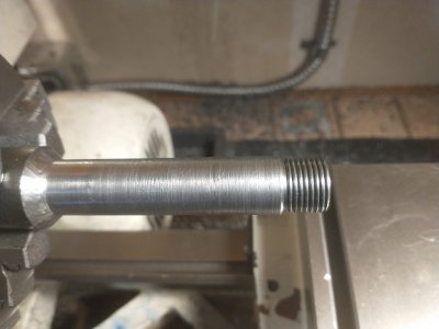
Was finally able to do the threaded rod using the single-point-threading technique after all the mechanical gymnastics. 5/8'' at 18tpi - chased the final thread with a round die for good measure. It's a good fit to the test base I made earlier. Overall pretty pleased with the outcome.
 

Attachments

  • thread_end1.jpg
    thread_end1.jpg
    207.7 KB · Views: 106
Bill - sounds like a nice solution for our lathes - can you share design drawing or at least a photo of what one looks like?
It took a while to find which archive drive had the file resident. There are a few photos at the end. It seems it is only 25 odd pages long, when I spoke of 40, it must have been for a different file. Feel free to pass this around, it is not copyrighted. The only restriction is that if the design is used for a commercial product, I want my cut. The PDF is an older version, there is no encryption. The contraption is not the most usable, especially for commercial work. But quite suitable for casual(hobby) work. The speeds listed in the chart are for the G1550, they may vary a small amount for other brands.

.
 

Attachments

  • HomadeBackGears.pdf
    2.2 MB · Views: 189
  • Rollie's_Dad's_Method.pdf
    12.5 KB · Views: 117
I bought a G1550 back in March of 1994 and never attempted to cut a thread on it till today because the lead screw was off it this whole time (long story). So anyway, after putting it all back together, shimmed and adjusted etc. to have it completely functional the 3/4 x 16TPI thread I attempted to cut was a total mess. I just couldn't figure out what was happening. Then I measured the lead screw and found it wasn't a 16TPI as stated but rather a 1.5mm pitch. The labeling on the lathe and the manual lists the lead screw as a 16TPI but it isn't.

My Harbor Freight 7 x 12 has an actual 16TPI lead screw and this is how I know for sure the one on my G1550 is metric.

So I'm thinking that I could possibly get a lead screw along with the other required parts from a G4000 to use on this G1550 lathe. Does anyone know for sure if the 16TPI lead screw from a G4000 is actually a 16TPI.

Thank you.
 
Here is an Owner's Manual for a Harbor Freight 14 x 40 lathe, probable pushing twenty years old now.
 

Attachments

  • Harbor Freight Lathe Manual.pdf
    1.7 MB · Views: 36
Back
Top