tool wear ?

bpimm

Active User
Registered
Joined
Nov 21, 2012
Messages
302
I'm retooling a part I make and am thinking that taking a deeper cut slower may end up with less tool wear. The mill is a grizzly round column that was converted to CNC, The part is cut out of 1/4" mild steel with a 3/16 4 flute either HSS or Carbide, I get the same tool life out of either. I'm taking .040 deep passes 3 from each side and am thinking that 2 passes of .060 deep and slowing down the feed rate to maintain the same tool deflection may get me better tool life because I'm using more of the cutting edge. Is my thinking correct?

Also I'm going to try to predrill entry locations so the tool wont be plunging into the material, If I can figure out how to manually place the leadin's with Fusion 360.
This is all happening as a learning tool for Fusion.

Thanks
Brian
 
It is not quite clear what you are doing. If possible, use the sides of the end mill to do the work. If possible, use the side flutes closest to the mounting end of the cutter, the sides will wear far longer than the cutting lips at the end of the end mill will. Save the end of the mill for when there is no other approach to doing the work, if possible.
 
You have missed out so much information it's impossible to even guess an answer!
Tool cooling and lubrication?
Does the part need to be welded? If not then you can use leaded steel!
How are you calculating your feeds and speeds? I use HSM Advisor which is very good, I don't find the built in figures in CAD/CAM to be as reliable.
 
Ok a bit more info, I had about 1 minute to write the question guess I didn't do very good...

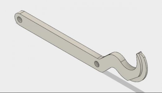
This is the tool I'm making
Single tool.JPG
it compresses valve springs 2 at a time, hooks under the cam and the blade goes between the valve shim buckets and the ramp pushes the bucket down and locks on the flat so the shims can be changed.

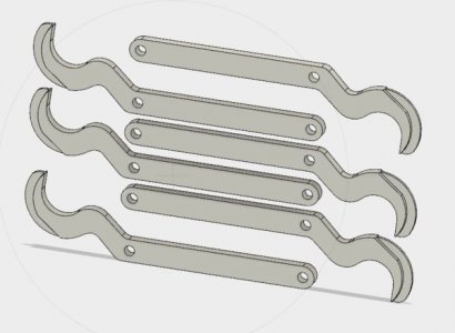
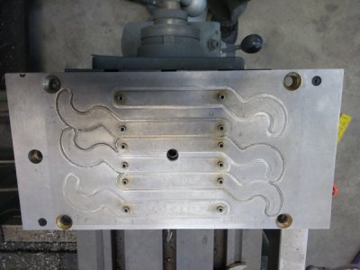
I make them 6 at a time on a fixture
6 tools.JPG
IMG_20171223_104304547.jpg
Each part is indexed on 2 pins and held down with screws, as it stands I used Alibre to design the part and Meshcam to do the CAM which is fairly limited in how it can set up the tool paths, it cuts the blade section down to finished depth then cuts the outline of the part in 3 passes of .040 each to get to the midline. The part is then flipped and it repeats the process to finish the other side of the blade and cut out. So it makes 6 passes at .040 plus the area of the blade plus it plunges strait down at the beginning of each pass. Mesh cam doesn't do lead in's or ramps just plunges and I know the plunges are not good on the tools.

Tools have been HSS or Carbide they last about the same I use up a tool on each side, if I try to get both sides out of 1 tool it breaks on the second side. I'm running flood coolant 1220 RPM and 4 IPM.

I use GWizard calculator for feeds and speeds.

My original question was would the tool life be better making 4 passes at .060 2 each side at a slower feed rate, I think about 3 IPM will still keep the tool deflection below .001 according to GWizard?

The other possibility I see is that all the plunges are killing the tool and less passes won't make any difference.

I'm in the process of learning Fusion 360 which is much more capable than the Meshcam is and I think I can set it up to plunge into a predrilled hole and eliminate the plunging all together, I just haven't figured out how to do it yet. It would be easy to add a few more holes in the program that pre drills the stock to fit the fixture.

How deep would you guys recommend cutting with a 3/16 endmill per pass?

Thanks
 
The tool looks like the tool I use to do the valve shims on my old Fiat (or VW).
Back in the 1970s I bought mine for $12.
 
I would suggest going to a 1/4" or better yet a 5/16" end mill. That way, you could take it all in one pass. Even a 3/8" end mill would be much better.
 
I would suggest going to a 1/4" or better yet a 5/16" end mill. That way, you could take it all in one pass. Even a 3/8" end mill would be much better.

To do that I would have to drop to 4 tools per batch, I'm using all of my Y axis travel as it is. Knowing what I know now I may have gone that route but for now I don't want to build a new fixture and there is only 0.220" spacing between the closest parts. For now I just want to see if I can improve the tool life for the existing fixture. It's not a high demand tool I'm running a batch of 6 every 3-4 months.
 
How about a roughing E'mill for the first pass . https://www.ebay.com/itm/SHARS-3-8x...alt-TiALN-Roughing-End-Mill-NEW-/302375658231 . I have no idea how much your machine can take , I think a HSS 1/4 rougher should be able to make the profile in one pass with a proper blast of water sol coolant . Only bummer is you will have to reprogram to leave finish stock . Sorry I can't help you with the CAD CAM , Last program I made was 15yrs. ago LOL .
 
Last edited:
there is only 0.220" spacing between the closest parts.

A 1/4 roughing tool isn't going to make it....

[Something Constructive, Tom, ] try full depth, 3/16 two flute, 700 rpm, 1.8 IMP feed.
 
Back
Top