Tool Offsets and Mach 3

Whew! Wow Fusion is different than Solidworks.

Okay so I was able to replicate the part I made in Solidworks and do the tool paths. Other than the tool numbers being different the g-code is virtually the same.

Test Block 1.png

Which post processor are you using?
 

Attachments

  • F360 Test 1.txt
    500 bytes · Views: 2
I'm not sure what you mean by use the Fusion table?

Fusion CAM has a built in tool library for various materials. Besides cutter physical features, e.g. cutter diameter, shank diameter, number of flutes, etc., the table contains speed and feed data. When you select a tool for a machining operation and generate gcode the speed and feed data is included.

Tom S.
 
Whew! Wow Fusion is different than Solidworks.

Okay so I was able to replicate the part I made in Solidworks and do the tool paths. Other than the tool numbers being different the g-code is virtually the same.

View attachment 234445

Which post processor are you using?
I'm using the Generic Mach3 Mill PP.
 
This is so very confusing and frustrating. I modeled the test block you suggested above, setup the CAM process using the default Fusion tool table, and generated gcode. The T numbers and H numbers match, which they should. I then generated gcode using the spot drill and 19/64" drill from my tool table. The T and H numbers match! To test further I opened my part file, the one that's been giving me grief, and reselected the appropriate tools from my tool table. Guess what? The T and H numbers match! Yesterday and last night they didn't. Not sure what's going on but the only thing I did was shut down Fusion last night and restart it this morning. This is so very strange. Now that I have what appears to be the correct code I'll do another air cut and see what I get. I'll report back.

Tom S.
 
Great, at least you are now getting the correct T & H numbers.

The CAM in Fusion is HSMWorks which I believe was originally a third party plug-in for Solidworks. This is what I use in Solidworks. Autodesk bought them a few years ago and incorporated it into Fusion with a different interface.

When you say "my tool table" I'm Assuming it is custom tool profiles you have setup in the Fusion tool library?
 
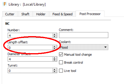
The only thing I can think of that would give you a H0 in the code would be if the tool number was not assigned to the Length offset on the Post Processor tab of the tool edit dialog. The "Number", Length Offset" & "Diameter Offset" Should all be the same.

Tool Setup.png

I'm not sure how you are doing it but when I use a pre-defined tool I will copy it and paste into my library and then edit it to assign appropriate parameters including the tool number.
 
Great, at least you are now getting the correct T & H numbers.

The CAM in Fusion is HSMWorks which I believe was originally a third party plug-in for Solidworks. This is what I use in Solidworks. Autodesk bought them a few years ago and incorporated it into Fusion with a different interface.

When you say "my tool table" I'm Assuming it is custom tool profiles you have setup in the Fusion tool library?

Yes, My Tool Table is a custom table I set up.
 
The only thing I can think of that would give you a H0 in the code would be if the tool number was not assigned to the Length offset on the Post Processor tab of the tool edit dialog. The "Number", Length Offset" & "Diameter Offset" Should all be the same.

View attachment 234457

I'm not sure how you are doing it but when I use a pre-defined tool I will copy it and paste into my library and then edit it to assign appropriate parameters including the tool number.

The offset boxes had the appropriate tool number inserted yet the generated gcode didn't come across with matching T and H numbers. I can only guess that when I opened Fusion yesterday something didn't load properly and the resultant gcode was not correct. Today is different. Just got done post processing the gcode and it looks fine. Next step is running an air cut. As you can imagine I'm gun shy. I've got my fingers crossed it will work.
 
Let us know how it goes. If you are still have an issue then we need to look at how you are imputing the heights in the Mach3 tool table.
 
Well that didn't go well. Ran an air cut for each of the four operations. The spot drill, rough contour, and finish contour ops worked fine. The 19/64" drill op still wanted to drive the drill through the vise. Thinking it may be a code issue I compared the spot drill code to the 19/64" drill code. Didn't take me long to figure it out. The spot drill code had G43 before the Safe Z move and the "H" command. The 19/64" drill code had G43 after the Safe Z move so the tool offset wasn't referenced for that move. Being that the 19/64" drill height is about 1.9" longer than Tool O I can understand why it was doing what it was doing. So I deleted the Safe Z move (still had retract/feed height set at .2") and ran the code. Worked perfect!

I have no idea why the post process put G43 after the Z move for that operation only. I'll look through my CAM setup, and probably post this on the Fusion forum, to see what I can find. I've looked at the post processor but computer language is over my head.

Jay - thanks for your help. It's always helpful to get another opinion.

For reference here is the gcode comparison.

Spot Drill 19/64" Drill
M5 M5
M9 M9
T8 M6 M1
S1075 M3 T9 M6
G54 S1075 M3
M8 G54
G0 X0.9448 Y-1.877 M8
G43 Z0.6 H8 G0 Z0.7
Z0.2 G0 X0.9448 Y-1.877
G98 G81 X0.9448 Y-1.877 Z-0.05 R0.2 F2.7 G43 H9
X1.9121 Y-1.3804 Z0.2
G80 G83 X0.9448 Y-1.877 Z-0.5 R0.2 Q0.0742 F2.7
Z5.000 X1.9121 Y-1.3804
G80
Z5.000
 
Back
Top