- Joined
- Feb 2, 2013
- Messages
- 3,820
I received a Vevor 1340 wood lathe for Christmas 2022 and started playing with it....
One of the shortcomings of the lathe is the inability to drill from the tailstock.
I took it upon myself to rectify that situation.
I purchased an inexpensive 1/2" capacity Jacobs' Keyless Drill Chuck .
it came tapped with a 1/2"-20 tpi female thread
![IMG_5296[1].jpg IMG_5296[1].jpg](https://www.hobby-machinist.com/data/attachments/398/398740-457b5d04ed24514b1bd13e82b7bc909f.jpg)
![IMG_5295[1].jpg IMG_5295[1].jpg](https://www.hobby-machinist.com/data/attachments/398/398739-5457f8ae858c48c96f8a0a06ce5a0e51.jpg)
I found a 10" piece of 304 Stainless M18x2.5 all-thread and a jam nut on ebay .
turned one end to 10MM to accept a handwheel
![IMG_5294[1].jpg IMG_5294[1].jpg](https://www.hobby-machinist.com/data/attachments/398/398738-e16e045be0b78ef4086fca9c234652f8.jpg)
I turned the opposing end to .500"
and single pointed the threads for 1/2"-20 tpi very close tolerance fit
![IMG_5293[1].jpg IMG_5293[1].jpg](https://www.hobby-machinist.com/data/attachments/398/398735-b321ab9fe19b89542de9dc3bc29b09fc.jpg)
![IMG_5292[1].jpg IMG_5292[1].jpg](https://www.hobby-machinist.com/data/attachments/398/398734-d6b39e199f85d15fbbf5a461055a4936.jpg)
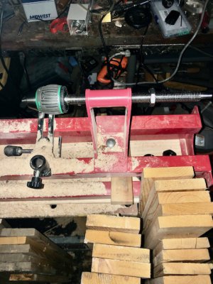
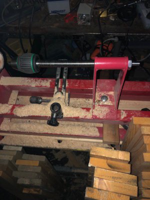
i removed the live center from the tailstock and installed the drill chuck


the full extension is approximately 5-1/4" with the jam nut
the next project will be turning a handwheel to utilize the retrofit
stay tuned if you dare!
One of the shortcomings of the lathe is the inability to drill from the tailstock.
I took it upon myself to rectify that situation.
I purchased an inexpensive 1/2" capacity Jacobs' Keyless Drill Chuck .
it came tapped with a 1/2"-20 tpi female thread
![IMG_5296[1].jpg IMG_5296[1].jpg](https://www.hobby-machinist.com/data/attachments/398/398740-457b5d04ed24514b1bd13e82b7bc909f.jpg)
![IMG_5295[1].jpg IMG_5295[1].jpg](https://www.hobby-machinist.com/data/attachments/398/398739-5457f8ae858c48c96f8a0a06ce5a0e51.jpg)
I found a 10" piece of 304 Stainless M18x2.5 all-thread and a jam nut on ebay .
turned one end to 10MM to accept a handwheel
![IMG_5294[1].jpg IMG_5294[1].jpg](https://www.hobby-machinist.com/data/attachments/398/398738-e16e045be0b78ef4086fca9c234652f8.jpg)
I turned the opposing end to .500"
and single pointed the threads for 1/2"-20 tpi very close tolerance fit
![IMG_5293[1].jpg IMG_5293[1].jpg](https://www.hobby-machinist.com/data/attachments/398/398735-b321ab9fe19b89542de9dc3bc29b09fc.jpg)
![IMG_5292[1].jpg IMG_5292[1].jpg](https://www.hobby-machinist.com/data/attachments/398/398734-d6b39e199f85d15fbbf5a461055a4936.jpg)
i removed the live center from the tailstock and installed the drill chuck


the full extension is approximately 5-1/4" with the jam nut
the next project will be turning a handwheel to utilize the retrofit
stay tuned if you dare!


