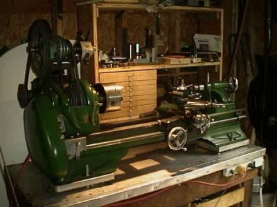
Spindle drive gears on Atlas / Craftsman 12 x 36

It looks like a completely homemade quick change arrangement. Probably works just fine as is, you'll want to cut some test threads to check it.
-Mark
Thanks for your input Mark....I'm hoping for the best. As a last resort I could always hunt around for the stock setup and just put it back to original.
I'm thinking that it won't be necessary....time will tell.
 
Sorry to be a bit late to the party. Once I get behind, it takes me forever to catch up.

I am inclined to agree with several others that it is a one-off done by someone. Totally different concept to the factory QCGB and the couple of after-market ones that preceded it. There is no front view photo of the headstock so part of this has to be a guess but the two shafts sticking out in the photo of the left end make me guess that the gear box is in the IN position and changing to the OUT position would result in the entire visible assembly sliding out, covering most of the exposed ends of the shafts.

The threading chart riveted to the inside of the gear guard is the original change gear chart and is not used. The other chart pictured is similar to the factory chart except for three things. On the factory chart, the coarsest pitch setting is shown on the left edge of the chart instead of one increment in from the left edge (this made me think for a few seconds that the GB would not cut 32 TPI!).

The factory chart only shows a single column of pitches for the "IN" sliding gear position.

And the bottom row of the chart is marked in TPI like the rest of the chart whereas on the factory one, the finest pitch numbers are in thousandths of an inch feed instead of in TPI.

At a guess, the original lathe was a very early 101.07403. This is based upon the presence of the individual gear guard over the bull gear. And the lack of a belt cover/gear guard covering the top of the headstock. Possibly the PO had removed that guard, as the earliest known parts list shows both individual gear guards and the one piece guard. Some time after introduction of the 101.07403, the two individual gear guards were dropped from the parts list. In any case, the serial number should still be found stamped into the right end of the front way.
 
Thank you for all your input and observations! The reason I was leaning away from "home made or one-off" was the outer support for the gear train is fairly thick and I was told by a machinist with 55 years of experience that the support was stamped metal.
But after reading your post I'm starting to believe that it most likely is a one-off. The stamped metal support still throws me...I don't know. The only thing that really matters though is that it works.
I took a better look at the chart on the QCGB....when you enlarge it you can see that it looks to be hand stamped and etched with a scribe....custom.
It might work well...and the chart on the QCGB might be accurate. Won't know till I get it back together in early spring and make some chips.
For some reason the Lord wanted me to end up with this one-of-a-kind...so I ain't gona argue with Him : )
 
I'm a pretty smart fella....I have thoughts I haven't even thunk yet. But I don't think I would have came up with that one.
That is a simple and great way to get some answers on the threading. Thanks!
I have no doubts you’re smart, I mean you joined this forum after all :> I can’t take credit for all of that. Mr. Pete’s YouTube videos gave me the idea on measuring the carriage movement with a dial indicator. I wish you continued fun with your new toy!
 
I'll have to check out Mr. Pete on youTube...one can only watch so much of the Three Stooges.
I've got it stripped down to just the headstock on the bed and will try to get the spindle apart today.
I'll have to hunt around on here and seen what's recommended as far as bearing replacements.
So far the only video I've looked at says not to spend the extra $$$ on class 3 bearings. That it would be overkill due to the machine's short comings. What do you think?
The only complaints I've read about the A/C's is that the power cross feed could be a little slower and that the longer beds are a little "springie".
I thought about a 2' x 6' x 2" granite slab with a support in the middle of the bed bolting it to the slab...added support and to damped vibrations.
The granite helped to cut down the vibrations on my little Unimat. Any thoughts.....all are welcome!
 
Mass will dampen vibrations, that is for sure. When I had mine, it was bolted down to a wooden bench. See photo. There was a lot of steel etc in the drawers under the machine!
Yes the power crossfeed is a little quick and it can be tamed by using a larger gear than the 64s that were included. The older lathes had 96s but not the 16/32 stud gear behind the spindle. Order a similar gear or 3D printed one to reduce the feed rate. I believe that the slowest feed was 0.0017”, but don’t quote me on that!
Pierre

658B16F3-15B3-4EB5-80E7-495CF1ADA1F4.jpeg
 
Last edited:
If you look around on the forum, I swear there’s a thread about the bearings recommended by others more knowledgeable. And my understanding is that the power cross-feed advances at the same amount of movement the carriage is set for. The lead screw powers both the carriage and the cross-feed, just not at the same time.
As for a/c lathes being less than stout, anything to add rigidity would be a big PLUS. For the bench, I’m not the person you want to get input from. I’ve got my lathe mounted on a rolling cart :)
 
Mass will dampen vibrations, that is for sure. When I had mine, it was bolted down to a wooden bench. See photo. There was a lot of steel etc in the drawers under the machine!
Yes the power crossfeed is a little quick and it can be tamed by using a larger gear than the 64s that were included. The older lathes had 96s but not the 16/32 stud gear behind the spindle. Order a similar gear or 3D printed one to reduce the feed rate. I believe that the slowest feed was 0.0017”, but don’t quote me on that!
Pierre

View attachment 387587
That's a nice lookin machine Pierre....good job.
 
If you look around on the forum, I swear there’s a thread about the bearings recommended by others more knowledgeable. And my understanding is that the power cross-feed advances at the same amount of movement the carriage is set for. The lead screw powers both the carriage and the cross-feed, just not at the same time.
As for a/c lathes being less than stout, anything to add rigidity would be a big PLUS. For the bench, I’m not the person you want to get input from. I’ve got my lathe mounted on a rolling cart :)
I'm gona forget about mounting it on a granite slab. I just ordered the bearings and races - 16150 / 16284B and 14125 / 14276B.
I'll be lucky to afford to mount it on a bed sheet from Goodwill. The bearings weren't that expensive but the "B" races with the flange on them...wow!
 
Here's a few pics of the spindle...looks pretty good but I've still got to measure it. The bearings were scribed with the date of
2 - 9 - 40. Eighty years...that a pretty good run. The races or cups weren't pitted but were just starting to show signs of wear at the inboard and outboard edges. Here's the link if anyone is having trouble finding them (I sure did): https://www.radwell.com/en-US/Search/?q=timken+16284B
$150 for the 16284B and $60 for the 14276B. I found them at other sites for about the same price...but the photos weren't accurate...no flange...so I didn't want to take the chance. Radwell took the time to list the correct photo so I went with them. Gona try and find some dry ice when it comes time to install them. Freezer might be good enough...
 

Attachments

  • DSCF4885.JPG
    DSCF4885.JPG
    34.5 KB · Views: 9
  • DSCF4888.JPG
    DSCF4888.JPG
    41.4 KB · Views: 9
  • DSCF4889.JPG
    DSCF4889.JPG
    40.9 KB · Views: 9
Back
Top