Spindle bearing play ?

compact8

Registered
Registered
Joined
Oct 13, 2012
Messages
350
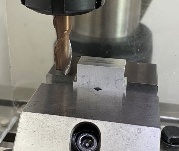
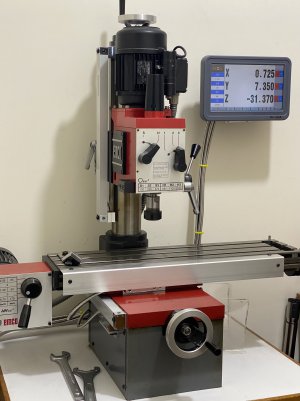
After fitting my EMCO FB2 with DRO ( Toauto, Chinese ) and calibrating it with guage blocks, I checked today if the effect of lead screw backlash is eliminated. I cut a vertical slot on a piece of Aluminium plate with a 10 mm carbide end mill. The depth of the finishing cut is 0.1 mm on both sides and the resulting slot is 0.02 mm narrower than that calculated from the DRO readings. Then I tried to cut the plate down to an intended width. The error is also 0.02 mm with the actual being wider. I can only imagine that this is due to the spindle bearing play which imposes an error of 0.01 mm on each side hence 0.02 in total. Any other thoughts ?

IMG_6021.jpg
 
Last edited:
One possibility is tool deflection which could be caused by flexing of the mill head or by play in the spindle bearings. Another possibility is an undersized cutter.
 
I agree it could be tool deflection. Did you have the head stock lock on when you made the cut? Did you have the spindle lock tight when you made the cut? I am guessing you made the cut with the x-axis, was the y-axis table lock on or vise versa if you made the cut in the y-axis? With small machines you need to make things as rigid as possible.
 
.02 millimeter is .00078".
What concerns do you have with a total spindle runout of less than 8 tenths of an inch?
What's the spec?
 
Spindle runout is not going to cause narrow slots and wide parts; it will do the opposite. Deflection seems likely. You have confirmed the DRO calibration is now accurate?
 
Thanks for all the replies. To answer some of the questions, the scales have been calibrated with guage blocks used as reference. The head stock was locked as well as the quill. The X and Y axes were not locked. Cutting was done along the Y axis and the X-axis DRO reading did not change in the process so it is unlikely that the error was caused by unintended movement of the table.

I have thought about the possibility of tool / head deflection but the cutting depth is just 0.1 mm and the material is aluminium so the loading on the tool / head is very low. The tool is a 10 mm diameter carbide end mill which should be very rigid. Can such light cutting load cause deflection ? Furthermore the tool was ran over the workpiece three times at the same table position so the cutting load in the final pass should theoretically be zero ? It's still puzzling for me ....
 
Last edited:
Were both cuts the same type? If one cut is a climb cut, and the other isn't, this can make a difference. Depth of cut, and tool geometry also affects the total amount of "tool pressure" which is exerted on the spindle. Smaller mills tend to have more "flex" than larger mills (but the truth is, all machine tools have some flex, even if it is microscopic).
 
Last edited:
Really need to see your setup to make any meaningful comments
-M
 
Back
Top