Small CNC build. Focus on keeping cost down.

Disk springs are pretty cheap, and should drop right in there if you have an issue. Pretty encouraging though. Have you had it under power yet?
 
Disk springs are pretty cheap, and should drop right in there if you have an issue. Pretty encouraging though. Have you had it under power yet?

No, last night I made a second pulley for driving it. It is a pulley on a 1/4 in shaft. I figure the best and cheapest way to drive it is the little trim router from HF. The only thing wrong with them is they have crappy collets with potentially pretty bad runout. Just using it as a motor seemed like a pretty good solution. They are actually pretty nice otherwise -- not to mention being $20. I have a cheap speed controller I can use as well.
 
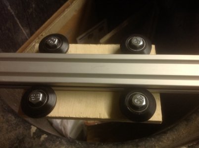
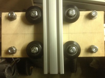
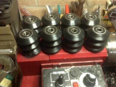
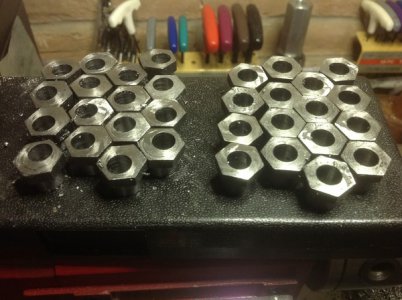
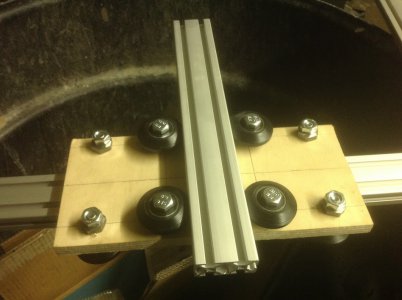
Ok, been sitting around without actually getting stuff built too long. Life sometimes gets in the way. I went back to some stuff I had made a while back and put them together. The wheels are delrin with 608z skate bearings pressed into them. The extrusions are 30 inch long (I think, I have never measured them) 2040 from the 8020 garage sale on ebay. They were $4 each. Each wheel has either a regular bushing or an eccentric made from 12L14 hex stock and turned down to 1/2 in for mounting. The hex screws are M8 with washers to space them off the extrusion. There is about 2 mm clearance between the extrusion and the plates.

I am not sure I am going to put the spindle I have been building on this one. That may be for the next one. It is a lot of complexity and I think I will just mount a HF laminate trimmer or a rotozip on this one for the spindle. Debating between #25 chain drive or 1/2-10 acme rod for drive. Once I get this one made, I can use it to make the other stuff I have in the planning stages.

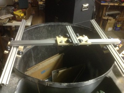
Garbage can for scale :)
IMG_0338.JPG
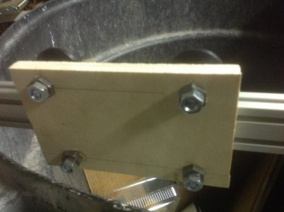
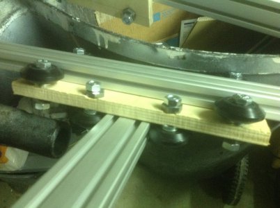
The cross slide for Y-Z is a bit wide but it sure simplified building. About 5 inches of Z travel. Not measured, just what I thought looked good.
IMG_0337.JPG
X rails from the inside.
IMG_0339.JPG
X rails from the outside.
IMG_0340.JPG
The back of the Y-Z plate.
IMG_0341.JPG
Front of the Y-Z plate.
IMG_0342.JPG
The wheels fresh off the lathe. I actually made two sets.
13+-+5.jpg

The eccentric bushing and the plain ones. I made enough for two machines.
13+-+1.jpg

IMG_0338.JPG IMG_0337.JPG IMG_0339.JPG IMG_0340.JPG IMG_0341.JPG IMG_0342.JPG
 
Have you measured play in those carriages? I am working on something similar for a 3d printer I am working on. I am building up the first carriage to test for play to see if it is viable (the other option is linear shafting and LM8UU linear bearings.
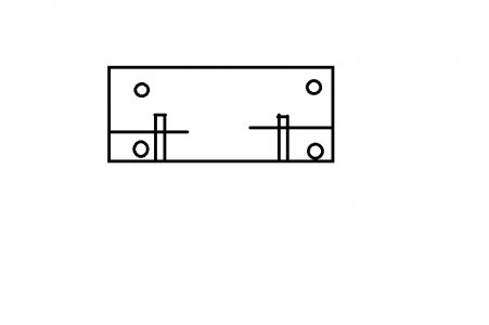
 
Have you measured play in those carriages? I am working on something similar for a 3d printer I am working on. I am building up the first carriage to test for play to see if it is viable (the other option is linear shafting and LM8UU linear bearings.

Yes, the play is none. :) Right now, they are pretty tight. They are also at the widest position of the eccentric. Another approach would be to use threaded inserts for mounting the wheels and use a cross screw with a slit to tighten them down. That would actually have a lower part count and be easier.

carriage.jpg
The linear shaft makes for a lighter moving assembly and smaller bearing unit but less stiffness. I think for a 3D printer, the speed is worth it. I have some other projects in the pipeline and am using polished rod and either bronze bushings or roller bearing units like the LM8UU (all the same but with 1/2 in shafting)

carriage.jpg
 
Back
Top