Small CNC build. Focus on keeping cost down.

David Kirtley

Active User
Registered
Joined
Dec 17, 2012
Messages
630
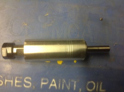
Ok, starting out now that I am getting other stuff out of the way. To begin with, I am starting with the spindle. I began with a 100mm long 8mm shaft ER11 collet holder that I got off Ebay for $16 with free shipping. It has been lost here in the house for since August and I finally came across it last night. :)

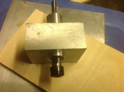
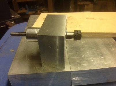
I tossed four 608 skate bearings in the oven on warm and the spindle in the freezer. I pushed 3 of them on the collet holder shaft and bottomed it out near the collet end.

Then I took about 4 inches of schedule 80 3/4-in 6061 pipe and bored it out to 22 mm deep enough for the three bearings on one end and deep enough for one bearing on the other. Did a little clean up on the outside diameter.

Did a very light press to get the bearings into the tube. Finally, I grabbed the last bearing from the oven and slid it down into the seat on the other end of the spindle.

Next I need to make a locking collar and a pulley. Then I can decide about the power and mounting bracket.
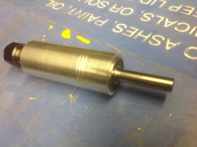
IMG_0320.JPG
IMG_0321.JPG
IMG_0322.JPG

I am still deciding on how to power it. The first options are one of two RC motors, both about 350watt with ESC. One is brushed, the other is brushless. The next option is to just put a pulley on a cheap HF trim router and run off of 120V. The final option is a sewing machine motor. Still deciding.

IMG_0320.JPG IMG_0321.JPG IMG_0322.JPG
 
Cute little spindle. Is this going to be for a small gantry style machine?
 
Cute little spindle. Is this going to be for a small gantry style machine?


Thanks. I am deciding on the size. I am working with some small drops of 2040 extrusions I got from 8020inc (8020 Garage Sale) on ebay.

I am also deciding to use some wheels I made up from delrin or blocks of UHMW-PE for bearing surfaces. Probably will be fixed gantry because it is easier to control depth for engraving. Circuit boards and other stuff.
 
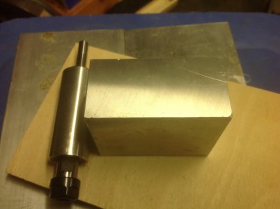
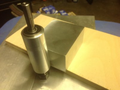
After rummaging around in my scrap pile, I finally decided on a piece of 1-1/2 thick x 3 in 6061 for the mounting block. I cut it off long enough to leave a land for the clamping bolts, the diameter of the spindle and some extra for mounting tabs on the sides.

I squared up the block in the mill with a fly cutter. I need a bit more practice as I didn't get it seated all the way down in the vise for some reason on one side. It doesn't matter as I am going to cut it off but still...

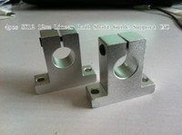
The block will be kind of like this:

4pcs-sk12-12mm-linear-rail-shaft-guide-support.jpg

But with a 1" hole. I might cut some fins in it for cooling. Depends on how much is left after cutting it out. I haven't done any measuring or layout on it yet. The spindle body will be about 1/4 in below the mount to give a little extra wrench room while changing bits.

IMG_0324.JPG
IMG_0323.JPG

I had to call it a night as it is laundry day. The clothes dryer vents into the garage and it gets pretty steamy in the garage while it is running.

4pcs-sk12-12mm-linear-rail-shaft-guide-support.jpg IMG_0324.JPG IMG_0323.JPG
 
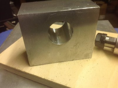
This is kind of sad. I spent all evening making one hole. Well, that's the breaks when you are using light weight machines with small capacity.

I laid out for the hole and started drilling. With the block up on parallels, I am severely limited on working space. I stepped through the drills with the sizes I have collets for. From 3/8 inch on up, I needed to remove the piece to be able to change drill bits. I set up a stop so it wasn't too bad. Just made it take longer. Once I was up into the Silver-Demming bits, low spindle power started to be a problem. I had to stop at 13/16. Then I switched over to the boring head. From then on, it was slow going at 5 thousandths per pass. Well, as long as you are making progress with each pass, it has to end eventually. If I ever do another one, I will go ahead and chuck it up in the lathe either on the 4-jaw or the faceplate. Either that or put it on a rotary table and get a long endmill.

IMG_0326.JPG
IMG_0325.JPG
IMG_0327.JPG

Next up will be layout for threaded holes and slitting. I do like the feel of the bore though. It fits really nicely.

If I do another one, I think I will just buy a Taig spindle :)

IMG_0326.JPG IMG_0325.JPG IMG_0327.JPG
 
Last edited:
Good luck on your project, I will be lurking to see your progress.:thinking:
 
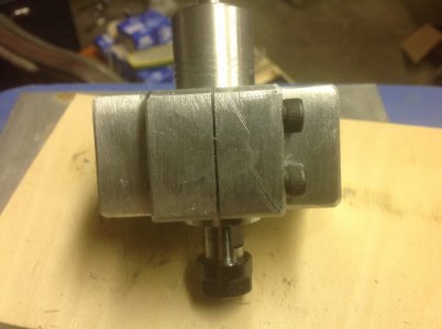
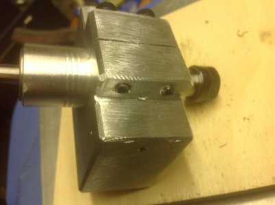
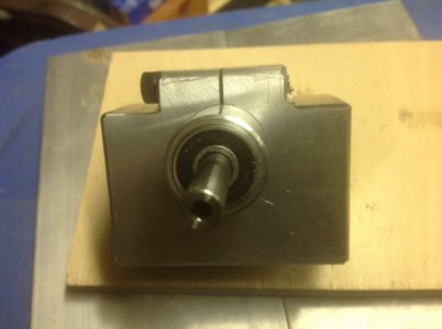
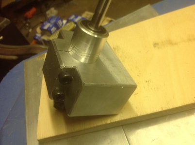
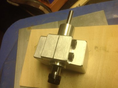
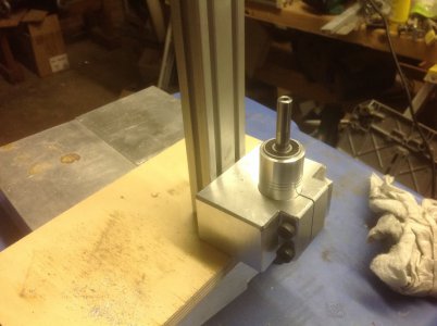
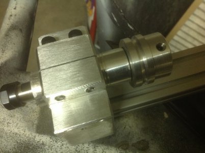
A little more progress. I finished the clamping. I used M6 SHCS. Just by pure luck, I ended up with the perfect length to get full engagement of the threads because it takes quite a bit of clamping force to squeeze that much metal. Knocked off the corners with a chamfer bit but mostly I just pulled out a big file. I can pretty it up if I feel like but this is really intended a proof of concept prototype. I have to force myself not to get too hung up on the details so I don't spend a thousand hours on it.

Not sure if I will cut cooling fins. I would prefer the mass but if I need to, there is enough metal to do some fins with the slitting saw. Got to test out my new arbor for the slitting saw. Worked great.

IMG_0332.JPG
IMG_0331.JPG
IMG_0330.JPG
IMG_0329.JPG
IMG_0328.JPG

IMG_0332.JPG IMG_0331.JPG IMG_0330.JPG IMG_0329.JPG IMG_0328.JPG
 
A few baby steps.

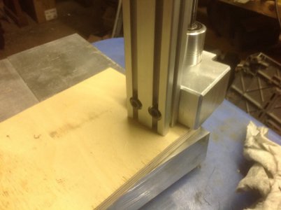
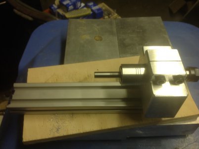
I drilled and tapped the mounting holes and also the extrusion to mount it on. You can see the part that comes out on the sides. I left that there so I can cut the cooling fins if heat becomes a problem. I just don't feel like cutting them right now. I need to think about the mounting of the linear rails and the leadscrew. I actually already have made the nuts for the leadscrew. They are for 1/2-10 Acme rod. The linear rails are also 1/2 in. I have not decided if I am going to capture the leadscrew between the top and bottom plates with bearings or just let it float. There is not much to whip around and nowhere for it to go. The top and bottom plates will be screwed to the linear rails and the extrusion.

IMG_0333.JPG
IMG_0334.JPG
IMG_0335.JPG

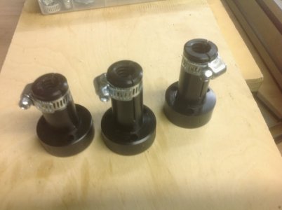
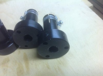
The leadnuts are delrin with high tech backlash adjustment mechanisms.
IMG_0283.JPG
IMG_0284.JPG
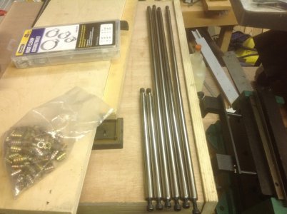
These rails are not all for this project. The short ones are for the z-axis of this project. They are scavenged from old printers and scanners. The bearings will be bronze bushings I picked up on ebay.
IMG_0288.JPG

IMG_0333.JPG IMG_0334.JPG IMG_0335.JPG IMG_0283.JPG IMG_0284.JPG IMG_0288.JPG
 
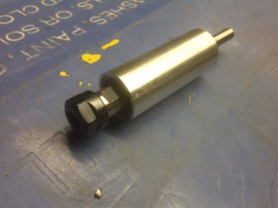
Pulley mounted. I am going for a single round sewing machine belt. From my best measurement using my perfectly calibrated Chinese DTI, I am getting in the range of 5 tenths runout on the collet bore.

I don't really think I could do any better with the tools I have at hand. Tenths are terribly expensive and that is against the goals of this build.

I put the belt down near the top of the spindle so I would have less leverage trying to pull it out of alignment once I get some tension on a belt.

Two 1/4-20 set screws 180 degrees apart for balance (I drilled one #7 hole straight through for both screws at the same time)

I went for a super scientific preload by just putting the whole thing in tension when I installed the pulley. There is an undercut with a boss on the bottom of the pulley to press on the inner race of the bearing.

IMG_0336.JPG

IMG_0336.JPG
 
Back
Top