- Joined
- Feb 2, 2013
- Messages
- 3,957
ACT 5
i got the saw in a relative state of readiness today,
although i have been working on the saw for a week off and on.
since the video,
i needed to get an electrical enclosure and contemplate mounting solutions.
the first thing i did was come up with a reference area to measure where everything was going to mount.
luckily the main casting had a trapezoidal feature.
the casting protrusion was going to be my mount point for the electrical enclosure.
the protrusion is a thick part of the main casting.
on the interior of the casting, there is a mount point for a brush for the lower wheel to keep chips debris from derailing the blade
i drilled and tapped the holes to 1/4"-20 tpi
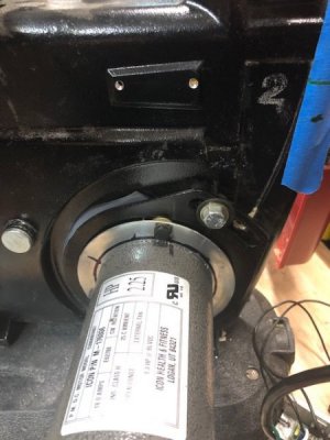
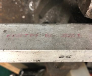
i cut a piece of reclaimed 1.5"x 1/2"x 6" 6063 aluminum and laid out the mount points on the electrical enclosure.
i transferred the holes and drilled the enclosure for the mount.
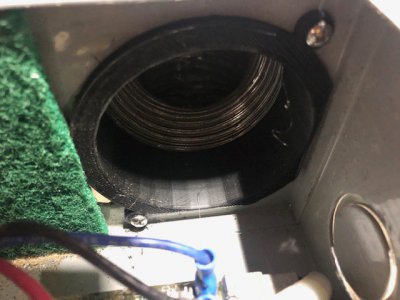
i drilled a 2-3/4" hole for the fan inlet and sandwiched an improvised nylon scrub pad filter and a small piece of expanded steel to keep the scrub pad out of the fan.
i tapped the fan mounting holes to #10-32 on 3 holes,
(the 4th hole had interference with the enclosure mounting )
)
the fan was sufficiently captured with 3 screws, so i'll live with it
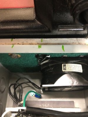
i mounted the KBMM-118 and the potentiometer to the enclosure, and plumbed rest of the the wiring through
when i made my video, i was ignorant to the fact that treadmill motors have a fan integral to the design of the flywheel.
that fact was pointed out ,astutely, by a good friend.
he made recommendation of keeping track of the motor temperature.
thanks for the thought and concern!
so with this in mind, i considered ducting the control box air wash through the dc motor.
i prepared by using a high volume/high speed 2-3/4" 115 vac fan,
to get a large volume of air circulating both through the control box,as well as using the clean air to cool the motor.
the wheels were set in motion,
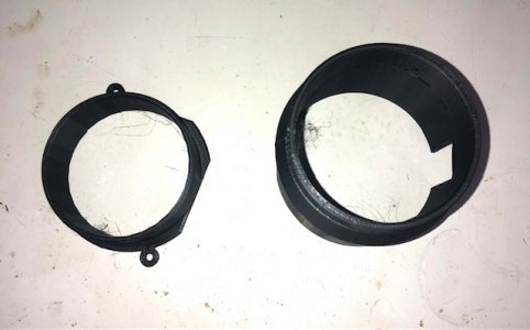
i drilled (read: and hacked) a 3" exit hole on the aft side of the enclosure.
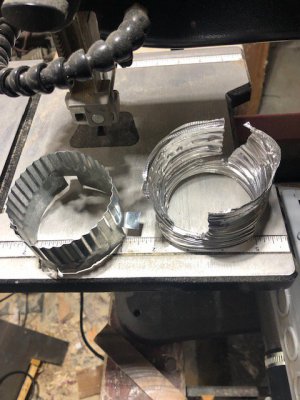
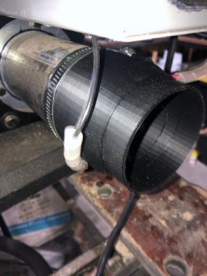
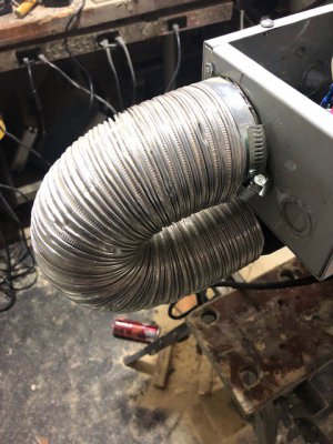
i used commercially available 3" water heater exhaust expanding aluminum duct and sheet metal couplings,
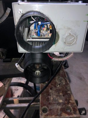
to rig up a 180° cooling elbow , from the big box store.
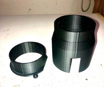
the fit was glove-like over the DC motor, i just had to notch for the carbon brush holders.
i was able to use a 3" clamp to hold it on the motor and box.
i added some anti-friction wrap on the potential wiring rub points.
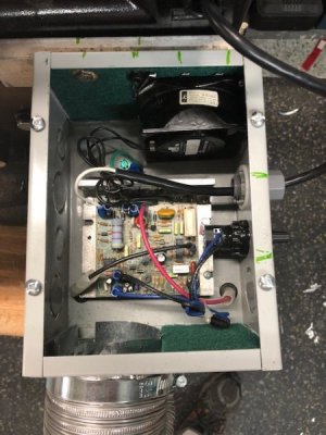
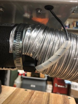
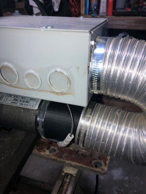
here is a side view,
the potentiometer is in the center knockout port.
i used the wrong port of the enclosure to hold the potentiometer ,
it was messing up mounting the incoming power to the enclosure.
there was only a 3/4" knockout there, so i fabbed up a bushing/spacer and washer for the 1/2" electrical fitting.
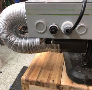
here is a picture of the control box, motor, and (questionable) cooling system, looking to the southeast
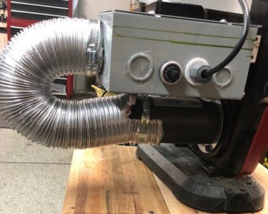
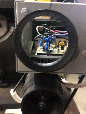
and one shot looking straight down on the enclosure
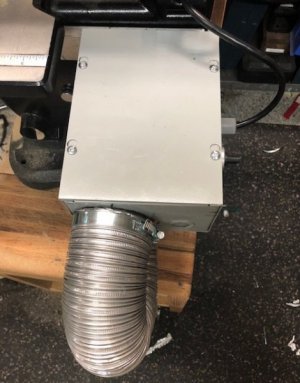
i taped over the enclosure knock-outs in an attempt to make the box as airtight as practical.
i still may add a gasket to the top cover, not that it fits poorly,
but just preemptively addressing the leaking cooling airflow to the motor.
let me tell you all, i did things the hard way on this build.
everything took twice as long as expected, but the performance is flawless
the retrofit, was less than flawless-
but, i'll take performance over appearance any day of the week
i'll be adding fuses for both the ac and dc circuits,
so the thread isn't over quite yet...
see you all on the next episode,
same bat channel, check your listings for times
drink your Ovaltine!!!
i got the saw in a relative state of readiness today,
although i have been working on the saw for a week off and on.
since the video,
i needed to get an electrical enclosure and contemplate mounting solutions.
the first thing i did was come up with a reference area to measure where everything was going to mount.
luckily the main casting had a trapezoidal feature.
the casting protrusion was going to be my mount point for the electrical enclosure.
the protrusion is a thick part of the main casting.
on the interior of the casting, there is a mount point for a brush for the lower wheel to keep chips debris from derailing the blade
i drilled and tapped the holes to 1/4"-20 tpi

i cut a piece of reclaimed 1.5"x 1/2"x 6" 6063 aluminum and laid out the mount points on the electrical enclosure.
i transferred the holes and drilled the enclosure for the mount.

i drilled a 2-3/4" hole for the fan inlet and sandwiched an improvised nylon scrub pad filter and a small piece of expanded steel to keep the scrub pad out of the fan.
i tapped the fan mounting holes to #10-32 on 3 holes,
(the 4th hole had interference with the enclosure mounting
 )
)the fan was sufficiently captured with 3 screws, so i'll live with it

i mounted the KBMM-118 and the potentiometer to the enclosure, and plumbed rest of the the wiring through
when i made my video, i was ignorant to the fact that treadmill motors have a fan integral to the design of the flywheel.
that fact was pointed out ,astutely, by a good friend.
he made recommendation of keeping track of the motor temperature.
thanks for the thought and concern!
so with this in mind, i considered ducting the control box air wash through the dc motor.
i prepared by using a high volume/high speed 2-3/4" 115 vac fan,
to get a large volume of air circulating both through the control box,as well as using the clean air to cool the motor.
the wheels were set in motion,
i drilled (read: and hacked) a 3" exit hole on the aft side of the enclosure.
i used commercially available 3" water heater exhaust expanding aluminum duct and sheet metal couplings,
to rig up a 180° cooling elbow , from the big box store.
the fit was glove-like over the DC motor, i just had to notch for the carbon brush holders.
i was able to use a 3" clamp to hold it on the motor and box.
i added some anti-friction wrap on the potential wiring rub points.


here is a side view,
the potentiometer is in the center knockout port.
i used the wrong port of the enclosure to hold the potentiometer ,
it was messing up mounting the incoming power to the enclosure.
there was only a 3/4" knockout there, so i fabbed up a bushing/spacer and washer for the 1/2" electrical fitting.

here is a picture of the control box, motor, and (questionable) cooling system, looking to the southeast

and one shot looking straight down on the enclosure

i taped over the enclosure knock-outs in an attempt to make the box as airtight as practical.
i still may add a gasket to the top cover, not that it fits poorly,
but just preemptively addressing the leaking cooling airflow to the motor.
let me tell you all, i did things the hard way on this build.
everything took twice as long as expected, but the performance is flawless
the retrofit, was less than flawless-
but, i'll take performance over appearance any day of the week
i'll be adding fuses for both the ac and dc circuits,
so the thread isn't over quite yet...
see you all on the next episode,
same bat channel, check your listings for times
drink your Ovaltine!!!
Last edited:


