bill70j:
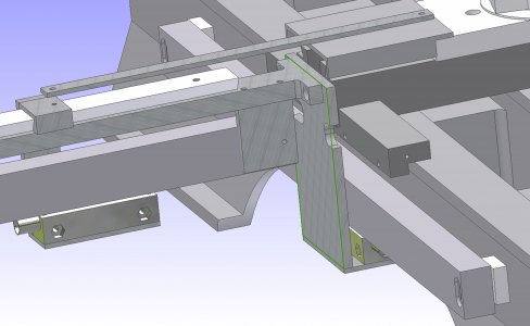
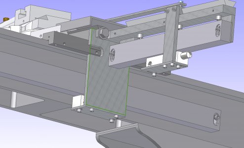
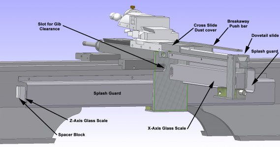
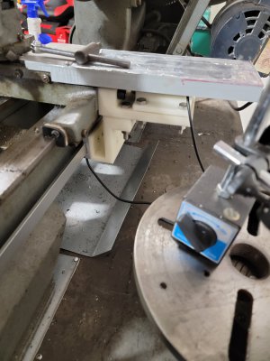
I'm planning on doing something similar on the long axis (X-axis, correct?). I see you mounted the aluminum block in such a way that it grips the screw heads holding the bearing plate. Any reason not to just screw the aluminum block onto the bearing plate using longer screws that replace the ones that hold the bearing plate? How well does your method hold the block on?

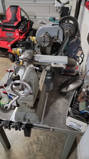
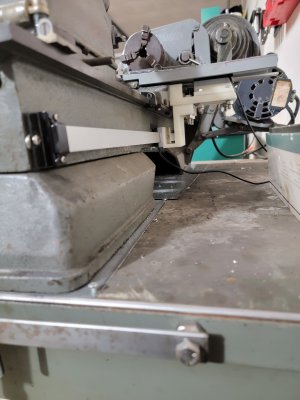
I want to use these screws to mount the block that holds the DRO. I thought I would just get longer ones. This plate just seems to hold the carriage on and not have any critical tolerances (or does it?):

The other option is to drill and tap holes in the bearing plate for separate screws. Thoughts?
CLARIFICATION
Just so I'm clear: is the X-axis is the long one (L-R as you are looking at the lathe/along the spindle axis) and the Y-axis is the short one (fore/aft; controls diameter of part)?
However, I thought the Z-axis was always the axis of rotation. In that case, using the right-hand rule-right hand, palm up, thumb to right, index away form you, middle finger straight up (so thumb is positive X, index is positive Y and middle is positive Z)-t if you orient your hand to point the middle finger along the axis of rotation, he long axis would be the Z-axis and the short one would be the Y-axis and there would be no X-axis.
I'm planning on doing something similar on the long axis (X-axis, correct?). I see you mounted the aluminum block in such a way that it grips the screw heads holding the bearing plate. Any reason not to just screw the aluminum block onto the bearing plate using longer screws that replace the ones that hold the bearing plate? How well does your method hold the block on?

I want to use these screws to mount the block that holds the DRO. I thought I would just get longer ones. This plate just seems to hold the carriage on and not have any critical tolerances (or does it?):

The other option is to drill and tap holes in the bearing plate for separate screws. Thoughts?
CLARIFICATION
Just so I'm clear: is the X-axis is the long one (L-R as you are looking at the lathe/along the spindle axis) and the Y-axis is the short one (fore/aft; controls diameter of part)?
However, I thought the Z-axis was always the axis of rotation. In that case, using the right-hand rule-right hand, palm up, thumb to right, index away form you, middle finger straight up (so thumb is positive X, index is positive Y and middle is positive Z)-t if you orient your hand to point the middle finger along the axis of rotation, he long axis would be the Z-axis and the short one would be the Y-axis and there would be no X-axis.
Last edited:

