Router Build

My apologies Jay. From page 36 of the User Manual:
View attachment 105674

D1 is the FOR terminal.
D2 is the REV terminal.

Perfect! .......well almost, in this configuration I can start/stop and fwd/rev the spindle with mach3 but cannot change the speed. It is always 100%.

What is odd is that with PD070 = 1 (0-5v) I get 100% (400hz). When set to = 0 (0-10V) I get 50% (200hz). My board is set for 0-10v pwm.
 
What is odd is that with PD070 = 1 (0-5v) I get 100% (400hz). When set to = 0 (0-10V) I get 50% (200hz). My board is set for 0-10v pwm.
Jay,

I'm glad the FWD/REV is working....

Yeah, I'm getting strange results with the same settings. It doesn't make sense to me. I tested mine using a 10k pot for remote speed control. It gave similar results. So I'm as confused as you are.... :confused:
 
Jay,

I'm glad the FWD/REV is working....

Yeah, I'm getting strange results with the same settings. It doesn't make sense to me. I tested mine using a 10k pot for remote speed control. It gave similar results. So I'm as confused as you are.... :confused:

Well I partially figured out one of my problems. The VFD control panel has a built-in potentiometer. It appears that this is interfering with the control inputs from the speed control board. I took the control panel out to see if I could disable the POT but I cannot get the knob off to pull the PCB out. I'm concerned I will damage something if I pull too hard. I tried swapping the control panel from my mill but as it turns out the settings are held in the control panel. I'd rather not mess up the mill so I'm leaving it alone. Not sure what to do now....
 
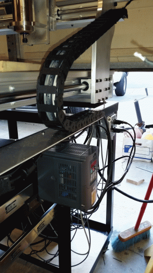
I finally figured it out. The VFD has an on-board potentiometer that was interfering with the output of the pmdx-106 speed control. There is a jumper in the VFD for on-board or external input. After making that change I had to change the wiring from the pmdx-106 to the VFD:

J6 NO --> FOR (VFD PD044 = 02)
J6 COM --> DCM

J8 NO --> REV (VFD PD0045 = 03)
J8 COM --> DCM

J2 LOW --> AGM
J2 SET --> VI

After making those changes I was able to run the calibration on the PMDX-106 and all is working as it should from Mach3.

Jay
 
That's GREAT Jay! :encourage:

Thanks for posting the working parameters. It helps me know more about the VFD. It also shows me I didn't know as much as I thought I knew. :confused:
 
That's GREAT Jay! :encourage:

Thanks for posting the working parameters. It helps me know more about the VFD. It also shows me I didn't know as much as I thought I knew. :confused:

I'm not claiming to know anything. Safer that way.
 
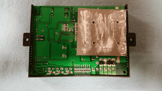
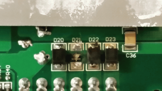
I pulled out the Z drive (DM860A) and found that a diode on the back of the drive board has exploded. That explains the pop I heard. Question is why did the diode blow?

It was fine with the old PS and BOB, at least during the times I was testing it. It happened after changing the power supply and BOB but it had been operating okay for a while before blowing. It blew shortly after powering up the VFD for the first time. Not sure if there is a connection there or just coincidence. The Gecko drives are operating fine.

Another thing is when the Z drive was still plugged in after it blew the diode I noticed the X & Y Motors were hotter than usual. After unplugging the Z drive the X & Y motors went back to normal temps.
 
Here is the back of the DQM860A. Hmmmm... somethings missing.....

Board back.gif board back close.gif
 
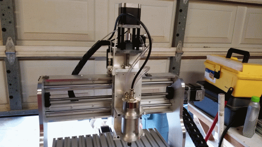
Alrighty....after several weeks of doing, undoing, redoing, ordering and reordering parts the electronics, I now have a fully functional machine! Sheesh I though this build would go smoother.

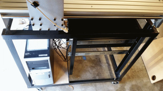
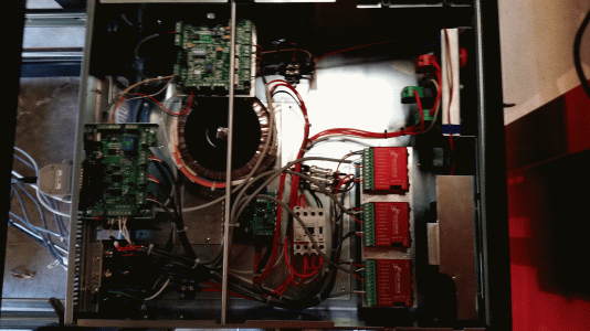
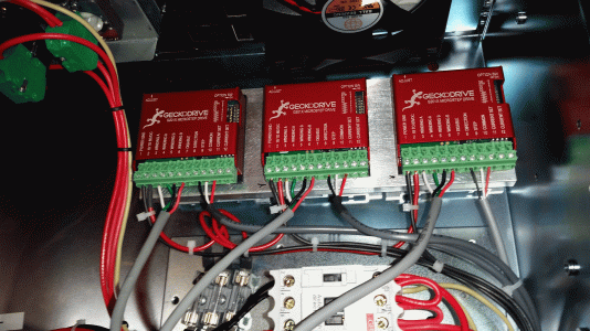
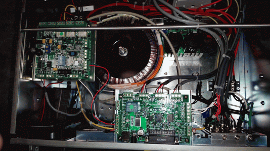
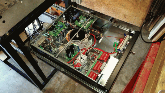
My plans to use most of the original components from the controller slowly went out the door. I have now replaced the power supply, breakout board, Geckodrives and removed the PC from the control box and installed it is a separate computer case. The control box now holds just the PS, BOB and Gecko's.

During the reconfiguration process I had dropped some copper wire trimmings in the case and some got into the mother board causing a fault. At that point I decided it would best to separate the PC from everything else. Fortunately the PC still works fine. With that out of the control box I reconfigured the layout to make things easier to service. It was kind of a nightmare with everything in one box.

The new Gecko G201X's are really sweet drives. Easy to configure, small form factor and tune the motors nicely plus they keep the motors nice and cool.

I had swapped out the original 34vd power supply for a 77vdc unit but after blowing the rectifier diodes on a Chinese drive I had on the Z-axis I replaced that with a 67vdc unit to give the Gecko's a little more headroom. I can't tell the difference in power from the 67vdc to the 77vdc units.

I have put the keyboard / monitor drawer on hold. I found a keyboard / monitor stand at a local computer surplus store for cheap so I am using that. Kind of a hack mounting job but it will do for a while. I may ditching the separate PC, keyboard and monitor and use a laptop on the stand with a better mounting job.

The spindle is a 1.5Kw 110vac water cooled unit from Automation Technologies along with a mating 1.5Kw 110vac VFD. I had not found much information on the 110vac spindles so I took a chance on it. I have not cut anything yet but so far it seems to run well. The VFD took a while to figure out the programming.

The typical Huanyang manual's can be tricky to follow plus they are for the 220/380 vac units, nothing in them about 110vac units. Fortunately I had gone through programming a Huanyang on my mill so I knew most of the parameters that needed to be entered. The only hiccup I had was the unit came with a built-in speed pot. That was interfering with the inputs from the spindle speed control board. Took me a while to find in the manual how to disable it.

Spindle cooling is a PC cooling radiator, 120mm fan and a small PC coolant pump. I'm hoping the single fan & radiator will be sufficient. I'm going to keep a close eye on temps for a while.

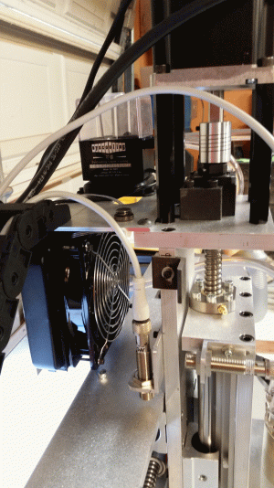
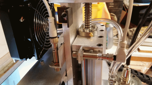
Just got done setting up the home/Limit switches and calibrating all the axis so it should be good to go.

Tomorrow I will pickup some MDF for the table top and see about running a test engraving program.

Jay
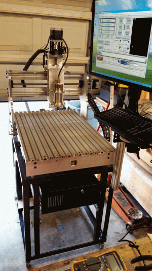
McrCNC01.gif McrCNC02.gif McrCNC03.gif McrCNC04.gif McrCNC05.gif McrCNC06.gif McrCNC07.gif McrCNC08.gif McrCNC09.gif McrCNC010.gif
 
Nice looking machine! Glad you got the bugs worked out.

Tom S
 
Back
Top