Rotary Vee Engine

rdean

Active User
H-M Supporter Gold Member
Joined
Feb 2, 2014
Messages
1,187
At the end of my last build there was some discussion as just what to build next.
(https://www.hobby-machinist.com/threads/single-cylinder-opposed.113501/ )
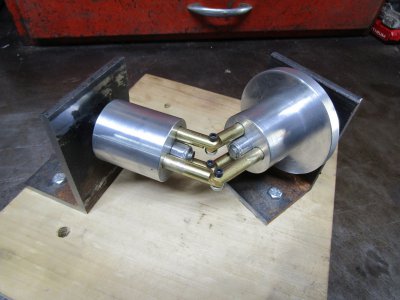
It was suggested that a rotary vee engine would a great project. There is some discussion of the engine there but I thought it would be better to start a new thread.
This is a video of an air operated version of the engine..

Eddyde added this information.
Here's an odd ball engine I have been obsessed with since I remember reading about it in Popular Mechanics Science magazine back in the 70's:
3912.png

Some info here:

At the present time this design doesn't seem to be advancing beyond the third prototype stage and that was in 1974.

It does interest me though and I will at least attempt to build an air operated version first. An internal combustion version is a remote possibility but who knows.

Thanks for looking
Ray
 
I will be using the Hobson coupling design and the Cardan joint to start out with. Combining these two features will make the alignment of the parts much easier.

Here is a video that explains these concepts.

Thanks for looking
Ray
 
I started with the cylinders in the milling machine. The three piston holes and the center axis hole must all be in alignment to each other. At this point the outside of the cylinder has not been turned true and I was not too concerned if it was even straight up in the vise. After the holes were drilled the cylinder was taken over to the lathe with an arbor in the center hole and the outside was turned to final size.
This gave me the best chance to get everything aligned properly.

IMG_3799.JPG

The video above and an article from Popular Mechanics magazine the December 1965 issue shows the pistons made in one piece and bent in the middle. I can only imagine the problems associated with that bend. All the pistons must be bent at the exact same angle and exactly at a 90 degrees. I don't want to try to do that if there is some other way. The Cardan joint should take care of that problem and you can see in the picture that is what I made. It swivels in the middle and will allow for the cylinders to be mounted at different angles to each other.
IMG_3803.JPG

Test fit.
IMG_3805.JPG

Progress so far
Thanks for looking.
Ray
 
Thanks Robert and Boswell.


Before I jump right in to making the side supports I want to see what kind of tolerances are needed for a smooth rotation.
I cut this piece of steel in half and drilled some holes for the axles.
IMG_3809.JPG

With the plates clamped down to my work bench I was able to turn the cylinders but with some difficulty.
IMG_3812.JPG

I found out just what I had expected. The axles must be in exactly the same plane as far as nod or rise is concerned. My angle iron supports are not 90 degrees either so first I need a better base and then a better alignment..
The angle of skew or turning one cylinder from being in line with the other cylinder to 90 degrees to it has little effect. The Cardan joint has taken care of that issue.

Thanks for looking
Ray
 
I mounted the brackets on a poplar board at a 60 degree angle and spent the rest of the day getting the cylinders to turn smoothly.
IMG_3813.JPG

This doesn't seem like it should be a big deal but the brass pistons are a close fit in the cylinders and they are binding. I have another reamer that is 0.001 over 3/8" so I will try that next.

Thanks for looking
Ray
 
Back
Top