Rotary Phase Converter Rebuild / Build

Eddyde

H-M Supporter - Diamond Member
Staff member
H-M Lifetime Diamond Member
Joined
Oct 13, 2014
Messages
9,577
Hi all, I just hooked up a used, Snyder brand, Rotary Phase Converter to my newly acquired lathe (more on that soon). It works but makes excessive noise & vibration, especially when running under no load condition. It sounds like its vibrating at 60hz so my thought is its electrical in nature, not mechanical. It is very loud at start up but quiets down noticeably when the lathe motor is running. The converter came pre-wired with a switch and a 3 phase twist-lock outlet, so all I had to do was hook the mains to it, thus I think it is wired correctly. Has anyone had a similar issue? Could it be bad capacitors?

Thanks

Eddy
 
It, for sure can be bad caps.

measure these volts L1-L2 L1-L3 L2-L3
goal is to get them within 10%
 
When you fire up the lathe the RPC is probably more in balance with the load on it. It really takes some tuning to get it in balance both unloaded and loaded. My manufactured leg is about 8 volts high unloaded. Were it not for the low mechanical rumble from mine you would hardly know it's running, pretty much just sounds like a motor running.

So as @Karl_T said, play with the caps a bit. Putting some caps across the line (power factor correction) can help also, I think I have about 40mF on mine.
 
What is it mounted to?

Mounted ours to top of post for car lift and very loud due to shapes of post.

Recounted with isolators and problem solved.

Sent from my SAMSUNG-SM-G930A using Tapatalk
 
Sounds like a tuning problem as Jim Dawson says. If it it fine under load, then your caps are likely fine. Under load, everything shifts including current and power factor. It is very likely that under the no-load condition, your caps are providing over unity power factor and the machine is bucking against the line frequency - resulting in the vibration. You may need to disconnect one or more caps when not loaded to see where the vibration stops. Of course, once the load is restored, the caps need to go back
 
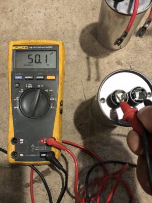
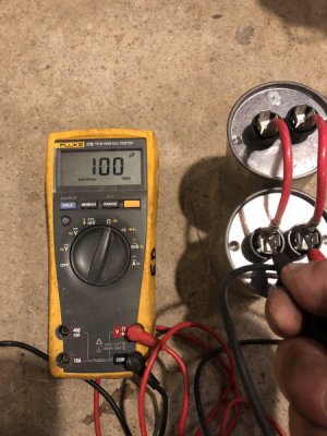
Thanks for the responses. I opened up the enclosure and found only 2 capacitors inside, there are no markings on them but they both tested to 50 microfarads, so 100 uF total, I assume they are okay.
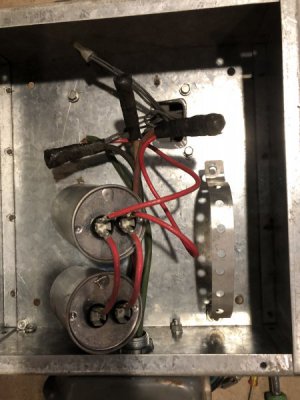
o1EkXR2MR2qtxR4s9Ifs8A.jpgfullsizeoutput_3193.jpegRqL23TsJScasJcmcYYB%+g.jpg
After reading up on info I found around the net, it appears the converter is wired in a simple "self starting" configuration. This is how its wired.
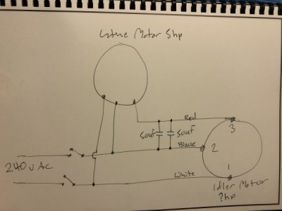
hNbF+8RTSTK5z75SdwZLgQ.jpg
The Info I read says the capacitor value should be 25-30 uF per hp for a self start circuit so that would mean the idler should only be 4hp max (there is no spec plate on the idler), which doesn't make sense as the spec plate says it can, and does, start a 5 hp motor and according to what I've been reading the idler should be twice the hp of the maximum motor to be started?
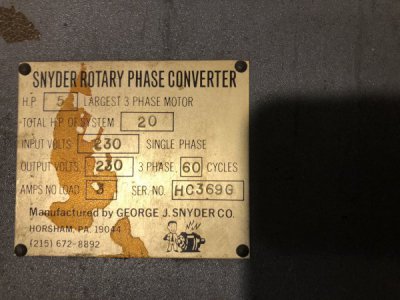
hdBU5UumTp6SxUJgRajbQw.jpg
So I first assumed increasing the capacitor values might help, but then I read, increasing the caps will increase the voltage which is already looking kind of high?
Line voltage, Between L1-L2, 246.1 no load, 243.4 with the idler and lathe motor, load.
Between L2-L3, 273.3v no load, 240.7v w/load.
Between L1-L3, 251.1v no load, 225.6v w/load.
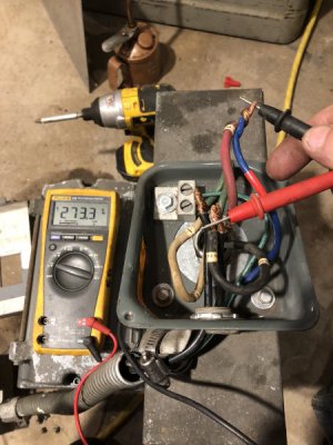
jFo+I7USToiEJw8UXKU12A.jpg
Being this is my first foray into Rotary Phase Converters, I am not sure how I should go about tuning this contraption, do I increase or decrease the caps or do I rewire the whole thing to a more advanced configuration?
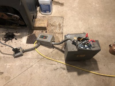
fullsizeoutput_3194.jpeg
The lathe is very quiet so this RPC is too noisy to use as is. Even under load, it is quite annoying. I am also not too keen on using a VFD for this lathe (I have them on other machines) as I don't need the variable speed option, I would need a 2nd VFD for the coolant pump and I don't want to have to rewire all the controls...

I appricheate your thoughts,

Eddy
 
Hi Ed, your system there seems kind of over-simplified, like old Mr. Snyder didn't quite get it (or was cutting cost to the max). Most systems I have seen have a separate start circuit set of caps and a relay or switch which drops them out after a short spin-up time, leaving the tuning caps in place. Check the internet, I have seen many diagrams and schematics
mark

Ha, it sure does looks like Mr Snyder was a little light on the engineering...
Originally, I was going to build the RPC from scratch, I was hunting around for a 10hp motor when this complete one crossed my path for $200. I figured it was ready to go and would save time and hassle, fool that I am...
So now I've been reading lots of articles and schematics on RPC design, trying to figure my next move. I would like to reuse the idler but don't know its horsepower rating so Im not sure how to calculate the cap values?
I'll probably go with a version of Jim's design, though perhaps not as fancy..
 
Back
Top