-
Welcome back Guest! Did you know you can mentor other members here at H-M? If not, please check out our Relaunch of Hobby Machinist Mentoring Program!
You are using an out of date browser. It may not display this or other websites correctly.
You should upgrade or use an alternative browser.
You should upgrade or use an alternative browser.
Rotary Phase Converter Rebuild / Build
- Thread starter Eddyde
- Start date
- Joined
- Oct 13, 2014
- Messages
- 9,631
Here s a first draft schematic:
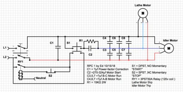
I may add a time delay relay for the start cap, as I have a couple on hand and may want to mount the start/stop switches remotely.
I over spec'd the motor start relay incase I need to ditch the idler I have and go up to a 10hp motor.
There will be disconnects and fuses between the idler and lathe motors.
- Joined
- Apr 30, 2015
- Messages
- 12,226
Looks fine Ed- you could also use a 2 pole relay if you don't have a 3 pole
M
M
Last edited:
- Joined
- Apr 30, 2015
- Messages
- 12,226
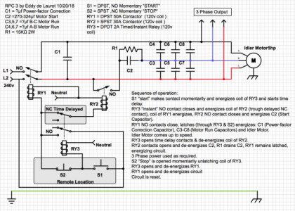
Ah I see now- RY3 is a time delay relay
If I'm not mistaken, you could eliminate RY2 if the TD relay had hefty enough contacts
I didn't know they made TD relays with both instant and delayed contacts- a handy device
If I'm not mistaken, you could eliminate RY2 if the TD relay had hefty enough contacts
I didn't know they made TD relays with both instant and delayed contacts- a handy device
Last edited:
- Joined
- Oct 13, 2014
- Messages
- 9,631
Sadly, RY3's contacts are only rated for a measly 2A "Non inductive"... No worries though, a proper contactor is on its way along with a whole bunch of other stuff, the gloves are off on this one!
Last edited:
- Joined
- May 20, 2017
- Messages
- 165
One grey area I'm still trying to understand is how to figure the power factor correction cap values?
As JD posted, connect the clamp on current meter to any incoming phase, and install caps one by one while watching the apparent power current drop. When you reach the point where another cap is no longer dropping the current, or the current increases, or the amount of current drop is not substantial, then stop adding caps. You do not want to go into the other direction with leading power factor as that can also cause vibration problems.
- Joined
- Oct 13, 2014
- Messages
- 9,631
Progress has been made, I hooked it up temporally to test it out, it worked very well, now the idler runs much smoother and quieter than before.
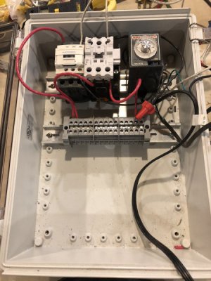
First I got the control relays and terminal blocks in place.
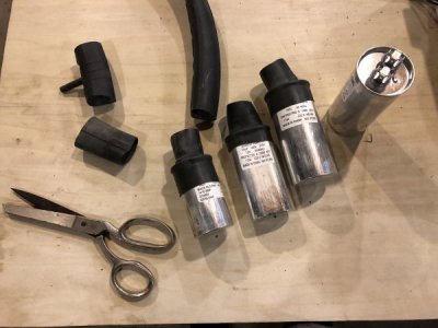
For extra safety, I made "capacitor boots" out of a bicycle inner tube.
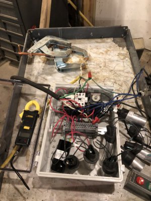
I did a preliminary capacitor balancing for the test, I'll do a more thorough job when I do the final assembly.
Control test
Run test
Next chance I get I'll hook it all up for keeps.

First I got the control relays and terminal blocks in place.

For extra safety, I made "capacitor boots" out of a bicycle inner tube.

I did a preliminary capacitor balancing for the test, I'll do a more thorough job when I do the final assembly.
Control test
Run test
Next chance I get I'll hook it all up for keeps.
Last edited:

