Restoration of my Schaublin SV52 toolroom milling machine

Hi all,
greetings to my "classmates" from the Georgia scraping class and our mentor R.King.

I have been trying to hone my scraping skills, as best I have had the time to (my friends camelback.. happens to be just the thing we practised, ie. one surface flat and to 40 ppi). I learned a lot in Georgia, something I would never have done without Richards teaching. I hope I will do him right with my efforts on my projects.. Another side of the class experience was that I had a he.. of a good time! Better vacation I could not have had.
One major project I have aquired is a Schaublin SV52 mill, details found at http://www.lathes.co.uk/schaublinmiller/page5.html (thanks to my friend Ola, who convinced me that I just had to have this mill, as can be seen by his grinning face after I had been talking with the salesguy at the local Danish machine dealer..)View attachment 54691

I did try the machine somewhat before committing, but as Ola proclaimed "it cannot be much used as there is hardly no paint chipped off.." hmm..the machine is a good 50 years old How well do you know Ola? That looks more like a "grin" then a smile...ha ha...is his brother the machine dealer? ha ha....Who took the picture, the dealer? The old owner may have used it very heavy for 1 year and it sat for 49 years in his storage.... ha ha (just kidding)
View attachment 54692pic of the mill in my garage, having been delivered by the typical Danish freight company driver working in slippers, truck with summer tires (down to my place went well, but in Oslo in the hillside in wintery conditions to where he went..?)
Well, to put it short, I have found both wear and breakage (as would be expected). You Danes are know for your relaxed (easy) state right? Slippers...ha ha ha that's funny
Listing as goes:
- The casting holding the brass nut for the in/out table feed was almost broken off, and parted entirely when I put it to the test.
A good lesson to block the machine between the top of table and column and top ram or spindle head. a 4' x 4" wood block. The used machine dealer should have know this. Ask him to pay for the cracked casting. Did your friend run the machine under power? When you buy a used car, do you take it for a test drive? Or just look at it?
One part is still stuck to the underside of the bigger part that onto which the table rests/slides. I have not yet been able to solve the puzzle of how to get apart, but I hope I am in for a "AHA!" experience. Anyway, the 2 cast iron parts are candidates for either brazing or welding together.. We'll see. That is a fix that may be held off until later. Update! I am told it is also possible to "nest the parts together" using Metalock. Ie. no heating, welding or traditional stuff.. sounds too good to be true.. will investigate further as there is a local Metalock company in my city. I have heard of it being used in big expensive castings. I would have it brazed by a pro. Look at the CA class or South Bend forum under "Ulma Doctor" he can tell you how to brazehe did some sweet work to his south bend compound.

- a couple of broken nuts/screw remaindings in holes etc. Not the biggest problems I would also do what Jim did check with the factory and see if you can buy new parts. Sometimes it sounds expensive, but when you spend hours making or fixing something a new one is worth the expense.
- Some more or less rusty parts. Also not much concern
- a lot of grime and dirt, as well as a good portion of greas/oil/swarf mixture.. again, no problem, just work..
- Then onto the topic that is more interesting, namely how much work is needed to restore it to its' former accuracy..
The old lady is Swiss, and on the heavy side at 1200Kg (2600lbs), so she's hard to wrestle around. I have plans to get her on her back having undressed her down to the bare neccessities.. that is, scraping the column ways et. Please be safe, buy, rent, make a A-Frame hoist to lift things (portable crane) or check with a local rigging company or tow truck operator to help you do it.

One thing I see you did not mention was the top round slide. be sure to check it and the rotating heads.


She may have a coat of fresh paint, but I am no artist, so if it can be avoided..Jim is a pro at painting as he does his antique cars. I would clean it and use a paint roller like we used for the ink and a quality paint brush, use a good quality primer and oil based paint. I have also used a Wagner electric paint sprayer, but it takes more work. Air painting makes a cloud of vapor and inside an attached garage will flow into your home...

The table sideways measurements shows about +/-5/100 (2/1000") deviation from center. To my knowledge, the table itself is bowed, and "hangs" down on each side by this amount. This is confirmed by setting a level on the table which proves it is high in the middle. Pic show one of the table flatness tests (I did front, middle and back as well as crosswise all corners, all the same results). Right, Richard. I think I mentioned the Professor who says the tables bend do to the peening of the tee slots and stretching the top of the table when they tightened the vise and parts down. He is right but I also believe it bends after years of unsupported travel or leaving it extended out unsupported for long periods of time. You may want to have the table top machined or ground and see if it bends back. You could scrape it, but it would not look original, you said the scraping on table? Was the table scraped for accuracy or was it just flaked / scraped for cosmetic looks?. If you are short of funds now scrape it as .002" 2/1000 isn't real bad. If you want to bring it back to new, it should be straight and parallel all over, dovetails, top sides, bottom flat's .0002"/12" 2/10000 in 12". The machine could be classified as super precision too and if it is .00005" / 12" 50 millionths in 12". Have to check that out with a sales catalog or a call to the factory.. I am assuming they are still in business?
View attachment 54693
The underside of table, ie. table ways, are pretty flat, though the scrapemarks are almost gone. I also measured the box ways after I had removed the table, leaving the knee ways exposed. In/out travel seems OK, ie. almost no difference. The horisontal ways seems to have seen less wear, and these seem flat and parallel. The main errors are in the vertical box ways. The knee slopes towards the left and out. Going down there is about 20/100 mm (8/1000") movement to the left from top to bottom (45 cm) and about 25/100 mm (10/1000") out.
Yes you need to do more detective work here and discover what ways are touching when new and what ones are clearance. To be honest I have never scraped this type of mill, but it is the same as others in the way it works Many times the center ways are the guiding ways and the outside ways are clearance. The gib screw maybe out of adjustment and you may need to put a temporary shim behind it to make your tests. You can mic the column ways at the top and bottom and these area are normally never worn and are original. Measure them and then in the middle. Remember what I said, measure clearance surfaced as they were machined at the same time as the ways and you can use them as a guide to find out the wear in the ways. Remove the sheet metal guards, those surfaces under there were machined at the same time the ways were machined and use a surface gage to measure from them to the ways. Be a detective, measure twice and cut once as the old saying says. You maybe able to write the factory and get the new machine inspection sheets to follow. Oh did you have your blade square tested?


View attachment 54697
The column has box ways, with the gib on the right (inside) of the left way as seen from the front. With this gib drawn in tight, there is still room for a 10/1000" feeler gage on the opposite side of the left way (same ways as the gib). This is probably because the left side of the righthand way also bears, so no matter if the gib is tight, there is still play. The top side of both keep-plates behind the ways also have play, indicating signs of wear of the mating members here, ie. the back of the ways?
The left side box way is higher than the right side, so it won't "sit" directly on the granite table. Therefore it seems easier for me to scrape the horisontal box ways while the knee is fixed to the column. See above on horizontal ways. I would say after you match fit the back of the knee and fit the rear hold downs I would also scrape the top of the knee on the machine so I can measure the squareness as the machine sets when it is assembled with the knee feed screw. You will want to leave the front of the knee plus at least .0001 to .0002" + in 12" so as you load the saddle and table on the knee it will sag from the weight. You may want to call the factory and ask them this question too. If the back of the knee has a worn area next to an original no worn area, depth mic this and if the wear is very bad, then you may want to make the front of the knee + .0005 to .001" plus. Also check to see if the oil holes are plugged. or pump to the back of knee is broken while being the detective as no oil could make it wear so bad. It might be possible the company who owned the machine seldom used the table, but bored holes feeding the knee up on a production job. Maybe you can call the used equipment dealer or look at the manual and discover who owned it before and give them a phone call and ask about the history of the machine. The picture below does not show way wipers as the one showing the front of the saddle. Is the way wipers on the Z Horz. ways? From the photo's I can't see where the gib is located and the opposite positive side on the knee where it touches or guides.
View attachment 54698

Scraping this will be a challenge with the stepped top, I will have to think about that, to get it square with the Z ways You may ask the factory how thick a shim to set under the one side of the square. Or use the saddle and straight-edge in combination to scrape the top of knee and set the square on the top of the saddle to measure with the blade square. I will let you know after I think about it. But if you measure the ends like I said and scrape off the same amount off each side and re-measure it as you scrape should keep it original...hmmmm this should work. Set the square on a parallel and gage block (s) to span the top ways. Remember what I said about straight oil grooves? You can see the area where the bottom of the saddle has straight grooves and left high areas on the top of the knee. Builder now seldom use straight oil groves in new machines because of that problem. You readers need to always put in diagonal oil groves in as they wear the complete matching way.


Is this OK practise? Out of lazyness, since the knee is already sitting there, I thought maybe I could scrape the horisontal ways first. OK? I guess this would void the term "building the house from the foundation and up"? Ie. normally you start at the bottom and work up: First remove the knee and scrape the column, then the mating member, then mount back the knee. See above.
Also, from your experience, which of the box way surfaces are clearance, if any? Left vertical way bears both sides, but is the right way meant to have clearance on one side? See above, measure the ends where they seldom wear and the clearance surface next to the wear ways.
Many questions, and I know you're progressed to another scraping class, but I thought you might like to hear from me... Kind rgds, Jan Sverre[/QUOTE

This will be a great learning project. Do your homework and clean the machine very well. Make sure to clean the dirty worn parts as you remove them and store them in plastic bags with labels. Never use a paper box, use a tin or plastic container. Check with the factory on what new parts cost. They will be more likely to give you engineering help if you buy new parts from them.
Take some more photo's and please ask more questions. You may also want to find a local retired machine rebuilder to help you. He might be sitting at home bored and would help for free, just to have fun again. Thanks Jan and have a great time scraping, Rich
:))

I attached some pic's of Jan that was taken last month in Georgia while he took my scraping class.
PS: I did not edit the other guys post, I hit the wrong "edit" post at the bottom of his post, thinking it was mine. OOoopppps , sorry.
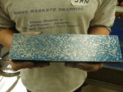
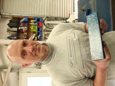
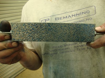
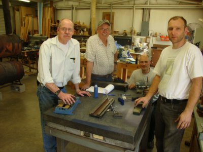
DSC01911.JPG DSC01910.JPG DSC01936.JPG DSC01939.JPG
 
Last edited by a moderator:
- He..he.. Ola and I are quite well aquainted by now, both being bitten by the "old iron bug". I was the photographer, so I plead quilty to the purchase of the "project". No blame to Ola.
We were in a hurry, so I knew we could have taken more time to evaluate and if it wasn't a ferry ticket and drive etc. away, would have had a 2nd look at it. I could then possibly have bargained the price down, so that is the lesson to learn. Anyway, I reasoned there would be hidden defects (yes, have done this before..) and I guess at that price all one get is UP- or "OOTG"-warranty (directly translated "out of the gate warranty..), so I kinda knew I was in for it.If I would throw out a wild guess on how long it would take just to dis-assemble, clean, paint and re-assemble, let alone all the alignment and scraping I
will try to undertake, I think the dealer show have given me the machine for free.. ha..ha
- Re. cracked casting,should have tested more, though honestly it did work when it was tried briefly under power. This one was a surprise defect. I may try to contact the dealer, but my expectations are low..On the positive side, the casting parts are now freed and I have learned some more about the complexities of this design. I am ready to take the part to our local welding shop for his opinion. He will also not rip me off totally for the job. We'll see what he says.
- Will have a look at the SB brazing post. Thanks!
- Will also contact the factory. However, though Schaublin is still in business, they make really expensive stuff so I might be in for a "fantasy price"
- Agree, re. the one-man-op working on heavy things, one cannot be too careful. There will always be situations you didn't plan/foresee, so a generous safety margin is needed.I have a general workshop mobile engine hoist, capacity up to 2t, so should do fine. The mill is now soon down to parts, and the column is actually a split, ie. 2 castings, whereas the foot is a casting by itself. This is also hollow and form a resevoir for the coolant
- The cylinder with the head mounting are now "loose", so will be removed and inspected. Pics coming
- Will take your advice on the use of the painting. Think I will just roller etc. No spray painting..
- Can have the table top ground, but I am more akin to scrape it, though this was not original. Well, we'll see how good I can be.. practise makes perfect..
Yes, Schaublin is still in business, but taken over by a consortium of machine dealers (maybe they went broke first?) I know a guy that are actually on "friendly terms" with one of the dealers, and they emply some old "scraping hands" to refurbish machinery. They might be able to give some hints. As you also say, maybe soem "old dogs" are bored spending their days with the wife at the mall.. longing for the workshop again..
- Really good advice Richard on the measurment/scraping of the table, column and knee! This is very much the info I seek! I have by now moved ahead and measured and investigated some more. The inner ways does seem to be the guideways, and the outer clearance. Gib is on the inner, left way. Looking at the videos I made of the up/down movement of the knee, it suggest to me that it is rocking some. Laying the gib on the surface plate showed it is bowed. The blade square specs says OK, but it is Chinese.. will test it against our other equipment at work.
I had removed the wipers already when I took the photos. Making more measurements (awaiting I muster up to flip the
column over), I have the knee all the way down, and I do tests with a straightedge on portion of the column flats. Same as will be done afterwards, but of course just on rougly half the length (the remainder being occupied by the knee), they are within 3/100mm (1.2/1000"). The horisontal surfaces are also good to within 3/100", using a feeler gage. Hmm, maybe I have done something wrong when I did the "live" tests.
OK. Will try your suggestion re, measuring the knee.
Yes, I remember you talking about the oil grooves. Actually, it seems someone has disconnected the oil pump, and used grease instead. Hmm..
What is the idea behind the stepped top? I mean, is there any advantage as compared to having them both at the same "level"?
PS! I have taken loads of pictures of the dis-assembly, and have tried to pack everything logically. Zip-lock bags are a good suggestion. Will contact the Swiss guys at the factory and at the dealers.
Thanks for all the answers Rich! Much appreciated that you take your time to go through and really get into the details. Will have more questions later.
Take care,
Jan Sverre
 
It sounds as if you have a handle on everything. Your question "What is the idea behind the stepped top? I mean, is there any advantage as compared to having them both at the same "level"? I am guessing the design was made that way as the raised way is the guide way and it's close to the feed screw and it looks like the table crank is on the left and heavier, so I would guess that's the reason. Ask the factory and see what they say. You can mic it too and get it parallel or make a surface gage with the pins and indicate it I look forward to helping, hearing what the factory says and if you can get a experienced factory trained helper. Rich

PS: Allan the host of the Wisconsin class bought Chinese blade square and it was off a mile....I think he said .008" 8/1000 and he had a real problem returning it. He bought it on Ebay from a large seller of squares and granite angles.
 
Hi everyone,

Still alive if someone wondered..
It has been a busy time lately, at all fronts, being a father, son, husband and employee, hence the hobby activities have suffered.

Anyway, I have managed to get the “beast” into manageable parts and moved them indoors (doing something in a non-heated garage in sub-zero temps in winter-Norway was not an option, therefore better move on while the “green-winter” (immigrant joke about the Norwegian summer) is still around..). As can be seen from the pictures, a “workshop moveable 1,5ton crane and a pallet lift are very handy. As is a strong, though somewhat reluctant helper (my son). He had the obvious answer to the obvious question after sweating the heavy iron to its’ present resting place: “Yes, it would have been better if you collected stamps”. He, he..

For those of you interested, som pics of the disassembly and movingView attachment 56790View attachment 56791View attachment 56793View attachment 56794View attachment 56795View attachment 56796View attachment 56797View attachment 56798View attachment 56799View attachment 56800


Now, since the thread wasn’t really to be about picking the mill to parts or moving it (though hopefully the pics are of some interest. The design of the mill is pretty complex, and I had some “aha, that’s how” moments. Good to have those pics when assembly time comes around).

After some cleaning of the column/ways, I have come around to the first inspection of the bare metal.

The initial measurements I did so far shows that the upper front surface of the boxed ways are flat within +/-0,01mm over its entire length (apprx. 900mm). The ends of each way are unworn, leaving 4 “pads” as reference. There is a faint ridge where the oil groove on the rear ways on the knee has been, which probably confirms what Richard said about this design and that makers nowadays prefer the zig-zag pattern (and the way he taught us in class when putting on the Rulon and making oil grooves). The ridge is however hardly detectable, and as best I could measure, must be less than 0,005mm (2 ten-thousand). The worn area is roughly where the knee would be expecting to spend its’ life, I guess, so no surprise. The straight-edge test would not allow a 0,02 mm (thinnest in my collection, rounding up to 1/1000 “) feeler gauge anywhere. I will of course blue it up and test. But, the straightedge pivots in the middle on top of the ridge on both ways, indicating a slight deviation from flatness. This is the same on both ways, as well as for the milled surface in between (though this center section is quite rough, it may still be used as reference? Further checks needed). I have tried different straightedges, and they measure the same (pivoting slightly at the same area). If I test beside the ridge, it is perfectly flat.. so there was a 5/10.000 bow in the ways originally?? Anyway, as far as I can measure, it is very close to flat.
View attachment 56801View attachment 56802View attachment 56803View attachment 56804View attachment 56805

The micrometer checks reveals that there is some wear in the same areas, but seemingly not more than 0,02-3mm at the most for the thickness of both ways (more numbers later..). I am not sure just how much wear to expect on the mating knee part, or if this checks out with the earlier “live” measurements, but have time to figure out. The width reading confirmed the same wear pattern, most deviation seen on the left way. This is the way where the gib rides on the inside (numbers later). However, wear does not exceed 0,03mm
View attachment 56806View attachment 56807View attachment 56808View attachment 56809

I will improve on the setup and do more measurements before commencing the scraping. As I was eager to get going, the mill column (I guestimate around 6-700Kg) is put onto 2 wooden blocks, and to get the tree points, I will split the block near the bottom part into 1 for each left/right sides and support the upper part of the casting with a screw jack, so I can adjust closer to level (I really would want a Kingway!). I am not at all convinced it will make a difference, but let’s see..

I will probably also measure the knee first before doing any scraping. As I measured the actual movements for the assembled machine, I would have expected more wear on the column, but that might indicate the knee being more worn. Or maybe the gibs were making problems? It will be interesting to see, going step by step through this.

And yes, I will not leave erroneous measurements out of the question. After all, I am an amateur.. but as such, I have the luxury of taking my time as no one is counting the hours I put into it

Holiday season emerges and I am due for a lazy fortnight on a small Greek island (Naxos)
Happy scraping,
Jan Sverre
 
First thing I want to say is I am so proud of you and all the students who are using what I taught them and your decisions to share here on Hobby Machinist. Thank You all.

Hi everyone,

Still alive if someone wondered..
It has been a busy time lately, at all fronts, being a father, son, husband and employee, hence the hobby activities have suffered.

Anyway, I have managed to get the “beast” into manageable parts and moved them indoors (doing something in a non-heated garage in sub-zero temps in winter-Norway was not an option, therefore better move on while the “green-winter” (immigrant joke about the Norwegian summer) is still around..). As can be seen from the pictures, a “workshop moveable 1,5ton crane and a pallet lift are very handy. As is a strong, though somewhat reluctant helper (my son). He had the obvious answer to the obvious question after sweating the heavy iron to its’ present resting place: “Yes, it would have been better if you collected stamps”. He, he..

Growing up and living in the Siberia of the USA I can relate to green summers. ha ha


For those of you interested, som pics of the disassembly and movingView attachment 56790View attachment 56791View attachment 56793View attachment 56794View attachment 56795View attachment 56796View attachment 56797View attachment 56798View attachment 56799View attachment 56800

I love the inner tire tube your using to support the ram, very cleaver :)

Now, since the thread wasn’t really to be about picking the mill to parts or moving it (though hopefully the pics are of some interest. The design of the mill is pretty complex, and I had some “aha, that’s how” moments. Good to have those pics when assembly time comes around).

After some cleaning of the column/ways, I have come around to the first inspection of the bare metal.

The initial measurements I did so far shows that the upper front surface of the boxed ways are flat within +/-0,01mm over its entire length (apprx. 900mm). The ends of each way are unworn, leaving 4 “pads” as reference. There is a faint ridge where the oil groove on the rear ways on the knee has been, which probably confirms what Richard said about this design and that makers nowadays prefer the zig-zag pattern (and the way he taught us in class when putting on the Rulon and making oil grooves). The ridge is however hardly detectable, and as best I could measure, must be less than 0,005mm (2 ten-thousand). The worn area is roughly where the knee would be expecting to spend its’ life, I guess, so no surprise. The straight-edge test would not allow a 0,02 mm (thinnest in my collection, rounding up to 1/1000 “) feeler gauge anywhere. I will of course blue it up and test. But, the straightedge pivots in the middle on top of the ridge on both ways, indicating a slight deviation from flatness. This is the same on both ways, as well as for the milled surface in between (though this center section is quite rough, it may still be used as reference? Further checks needed). I have tried different straightedges, and they measure the same (pivoting slightly at the same area). If I test beside the ridge, it is perfectly flat.. so there was a 5/10.000 bow in the ways originally?? Anyway, as far as I can measure, it is very close to flat.

I would guess it bows in the middle because as I teach, the dirt gets in on the ends and wear there and the ways get high in the middle. I just saw this on a rebuild of a Nikkon Centerless Grinder too. This is why I always lower the middle .001" to .0015 lower in the middle 40%. Your machine was probably built that way too and it has worn so it is high now. The picture of indicating the center area that looks like it's painted is not something that looks real good to me. Does it look to you it was once a smooth surface? It appears in the picture to be a rough casting. I do teach the students to check the non wear surfaces that were no doubt machined at the same time the way surfaces were machined. On a Swiss, German, Japanese British, European, Taiwanese and USA machines I would say that is the norm, but after seeing some of the Chinese machines I would not say that can be trusted. I am glad you saw the problem with cutting a straight oil groove is. Even though yours is so small. But be sure to scrape it off first before scraping using the blue on your straight-edge. Remember to remove all ridges first after you measure them.

View attachment 56801View attachment 56802View attachment 56803View attachment 56804View attachment 56805

The micrometer checks reveals that there is some wear in the same areas, but seemingly not more than 0,02-3mm at the most for the thickness of both ways (more numbers later..). I am not sure just how much wear to expect on the mating knee part, or if this checks out with the earlier “live” measurements, but have time to figure out. The width reading confirmed the same wear pattern, most deviation seen on the left way. This is the way where the gib rides on the inside (numbers later). However, wear does not exceed 0,03mm

Remember what I said about leaving the top of the knee slightly high in front and if you look at the book Petras (one of the other students who was super computer friendly and found a copy on the net) sent you links to and the copy I brought to the class "testing machine tools" it will show that test. I am also impressed with the design of the back of the knee as to the ratio of the way surface to the top of the knee. I would suspect as you do, it will probably be the rear hold-downs that so more wear then the knee. On Bridgeports, they are worn on the bottom 2 pads of the knee flat ways and the top dovetails are where the wear is.

View attachment 56806View attachment 56807View attachment 56808View attachment 56809

I will improve on the setup and do more measurements before commencing the scraping. As I was eager to get going, the mill column (I guestimate around 6-700Kg) is put onto 2 wooden blocks, and to get the tree points, I will split the block near the bottom part into 1 for each left/right sides and support the upper part of the casting with a screw jack, so I can adjust closer to level (I really would want a Kingway!). I am not at all convinced it will make a difference, but let’s see..

When I taught all those classes in Taiwan we did experiments using 3 points and of the dozens of machines we did over a couple of years of testing we found 3 points was a key to getting proper alignment. I am so happy to see you thinking about it, as I feel using 3 points is also a lost art. You have the pictures of the King-Way so you should be able to make one or some sort of sled or T-shaped device to set your level (s) on. Also remember when your taking the measurements the very top and very bottom seldom are worn, so you can use the end on those box ways to keep the geometry the same as it was when new.

I will probably also measure the knee first before doing any scraping. As I measured the actual movements for the assembled machine, I would have expected more wear on the column, but that might indicate the knee being more worn. Or maybe the gibs were making problems? It will be interesting to see, going step by step through this.

You may find it out of square because it was made that way new High in front. When you measure the knee off the machine for squareness on a plate don't be surprised to see it that way, so keep that in mind when you test it. As I teach, I would make those final squareness tests when the knee is standing up on the column and the weight is balanced on the elevating screw as it will be when assembled.

And yes, I will not leave erroneous measurements out of the question. After all, I am an amateur.. but as such, I have the luxury of taking my time as no one is counting the hours I put into it.

Yes as my father in law who was a woodworker hobbyist used to say, measure twice, cut once. :)


Holiday season emerges and I am due for a lazy fortnight on a small Greek island (Naxos)
Happy scraping,
Jan Sverre

My wife and I loved Corfu, Have a relaxing trip.
Rich

PS: I am glad you are showing your son to rebuild....Pass on your knowledge. I never enjoyed stamp collecting, to boring!

 
Last edited by a moderator:
Thanks Richard!
You inspire me to go at it.. maybe I should stay in the hobby room instead of going to Greece..hmm?

Growing up and living in the Siberia of the USA I can relate to green summers. ha ha
That was a good one! I guess you also know much about prepping for winter. My wife kept pestering me about our bedroom being too cold, and when I (finally) went at it, I saw the former owner had left the insulation of the outer wall completely. No wonder I measured -4C at the floor level when it hit -25C outside.. it was a "no-brainer", to give "room" for hobby, it is now fixed (interpret it the way you want)

I love the inner tire tube your using to support the ram, very cleaver :)
Yeah, well.. it is actually one of those new fangled excersize balls.. it had to be used for something, even deflated. It did the trick. Ram & head was probably 100Kg alone, so was not easy to handle. I guess this is where the designers built a degree of smartness into the machine.. you can turn the spindle in each angle you want, and in the horisontal mode you can extend 2 hefty bars and put a long arbor in use with support the usual way (though for my use I doubt if I ever need that)

I would guess it bows in the middle because as I teach, the dirt gets in on the ends and wear there and the ways get high in the middle. I just saw this on a rebuild of a Nikkon Centerless Grinder too. This is why I always lower the middle .001" to .0015 lower in the middle 40%. Your machine was probably built that way too and it has worn so it is high now. The picture of indicating the center area that looks like it's painted is not something that looks real good to me. Does it look to you it was once a smooth surface? It appears in the picture to be a rough casting. I do teach the students to check the non wear surfaces that were no doubt machined at the same time the way surfaces were machined. On a Swiss, German, Japanese British, European, Taiwanese and USA machines I would say that is the norm, but after seeing some of the Chinese machines I would not say that can be trusted. I am glad you saw the problem with cutting a straight oil groove is. Even though yours is so small. But be sure to scrape it off first before scraping using the blue on your straight-edge. Remember to remove all ridges first after you measure them.

The area between the ways is rough milled, but maybe too rough to be useful. There are 2 definite lines along the length, indicating it was milled in 3 strokes, though the mill marks indicates a larger diameter mill. Anyway, I may not need this surface. I have used citrus-rinse to clean up the mill (I have been nagged about smelling gasoline or similar so often that I thought it was a good idea to try this). Seems to function OK. There are some marks on the surface.. pitted (rust!)
The mill is supposedly of very good make, but of course it is a long time since it has been born, and she has seen some use I am sure. It is anyway made properly, though "over-engineere"d in many respects (for example the former mechanical design for stepless speed control now perhaps being better soved with a VFD?)

Yes, I will take away the ridge first and scrape it flat.

The oil-groove on the back side of the knee ways confronts me with a possible challenge: Do I retain the ways as is, of course correcting the geometry and scrape as best I can, OR do I rough mill it out and put on Rulon/Turcite, and make the zig-zag groove recommended? The 1st option seems the easist, and it will brobably "outlast me" anyway, but the 2nd option will give some hands-on training, though it might be better to practice on smaller items first. Will give it some thought

Remember what I said about leaving the top of the knee slightly high in front and if you look at the book Petras (one of the other students who was super computer friendly and found a copy on the net) sent you links to and the copy I brought to the class "testing machine tools" it will show that test. I am also impressed with the design of the back of the knee as to the ratio of the way surface to the top of the knee. I would suspect as you do, it will probably be the rear hold-downs that so more wear then the knee. On Bridgeports, they are worn on the bottom 2 pads of the knee flat ways and the top dovetails are where the wear is.

Will read-up on this again (fantastic book btw..). I am eager to do those mesurements, and also to find out how/if they correlate with the "real-life" measurement, travelling up/down

When I taught all those classes in Taiwan we did experiments using 3 points and of the dozens of machines we did over a couple of years of testing we found 3 points was a key to getting proper alignment. I am so happy to see you thinking about it, as I feel using 3 points is also a lost art. You have the pictures of the King-Way so you should be able to make one or some sort of sled or T-shaped device to set your level (s) on. Also remember when your taking the measurements the very top and very bottom seldom are worn, so you can use the end on those box ways to keep the geometry the same as it was when new.

I will put the casting on 3 points before I leave for holiday! As I now know about this, it seems so obvious. I wish I had more brains so I could also think logic like this.
Same thing with the spin-test, I mean to find the Airy-points as you described and showed us. So very logical! Why cannot I find out myself.. I am alos amazed how sensitive you can make this test, and to which degree it seems to be possible to test the surface just doing that.

I am thinking about a sled as you suggest. When I get the casting reasonably level, I should be able to use a machinist level on top of the sled in combination with a normal indicator (sort of a "cumbersome to use" Kingway). I see how the need for a Kingway emerged..

I am also wondering if I am able to scrape the undersides. Hard to get to these areas, as I cannot envision myself flipping this casting over. Is it wise to think about grinding these, rigging up some contraption? I guess not..? A dovetail like the Bridgeport is handled while having the column laying as mine?

Yes, my plan was to use what seems pristine areas of the ways, what appears to be scraping marks still visible

You may find it out of square because it was made that way new High in front. When you measure the knee off the machine for squareness on a plate don't be surprised to see it that way, so keep that in mind when you test it. As I teach, I would make those final squareness tests when the knee is standing up on the column and the weight is balanced on the elevating screw as it will be when assembled.

OK. Shall keep in mind. This knee way design is a bit ackward in comparision with a Bridgeport as you cannot set the knee directly on table. It is an X, so to speak, both ways crosssing each others paths. The vertical surfaces extending further up than the horisontal ways, as well as the horisontal ways "blocking" as they extend further back than the vertical ways. Makes sense to out on granite table anyway, onto necessary high gage blocks? Or just test directly on the (by then) flat column ways?
I guess you have come across this or similar situations, and had to think alternatives..

Yes as my father in law who was a woodworker hobbyist used to say, measure twice, cut once. :)
Wise statement!

My wife and I loved Corfu, Have a relaxing trip.
Rich

Thanks.. will enjoy.

PS: I am glad you are showing your son to rebuild....Pass on your knowledge. I never enjoyed stamp collecting, to boring!

Will try, but as for now he seems more into hanging out with friends etc. than listening to dad
Tried stamps.. fun for awhile, but they fell down the ranking list. However, I guess it is good we are not all alike.
 
[h=2]Re: Restoration of my Schaublin SV52 toolroom milling machine[/h]
Thanks Richard!
You inspire me to go at it.. maybe I should stay in the hobby room instead of going to Greece..hmm?

If you do that, you will be a proud member of the :nuts: rebuilding society...........:rofl:​
 
I tried to edit the questions and comments from Jan and my answers......sorry if it is confusing, but I can't figure out how to change the color of the font. Rich


Thanks Richard!
You inspire me to go at it.. maybe I should stay in the hobby room instead of going to Greece..hmm?

Growing up and living in the Siberia of the USA I can relate to green summers. ha ha
That was a good one! I guess you also know much about prepping for winter. My wife kept pestering me about our bedroom being too cold, and when I (finally) went at it, I saw the former owner had left the insulation of the outer wall completely. No wonder I measured -4C at the floor level when it hit -25C outside.. it was a "no-brainer", to give "room" for hobby, it is now fixed (interpret it the way you want). We all know who the boss is..lol...I have been in love with my lovely boss for 38 (I think) years Don't tell her I forgot...lol....In my first house that was built in 1940 we had a upstairs bedroom with pine tongue and groove paneling on the walls. In the winter it was cold as the north pole up there. I installed new windows up there and discovered the insulation was 4 layers of newspaper. LOL.......I had insulation foam pumped into the walls. Really made a difference. I suspect the old owner preferred it cold as I discovered the boss didn't cuddle for the warmth after that...lol

I love the inner tire tube your using to support the ram, very cleaver :)
Yeah, well.. it is actually one of those new fangled excersize balls.. it had to be used for something, even deflated. It did the trick. Ram & head was probably 100Kg alone, so was not easy to handle. I guess this is where the designers built a degree of smartness into the machine.. you can turn the spindle in each angle you want, and in the horisontal mode you can extend 2 hefty bars and put a long arbor in use with support the usual way (though for my use I doubt if I ever need that)

(Rich) That is funny!! A Exercise ball....I bet it was a Christmas present from the boss? Those old machine designs were made to last for years. Can't imagine seeing many of those cheap Asian imports being rebuilt after 60 years of dependable service.


I would guess it bows in the middle because as I teach, the dirt gets in on the ends and wear there and the ways get high in the middle. I just saw this on a rebuild of a Nikkon Centerless Grinder too. This is why I always lower the middle .001" to .0015 lower in the middle 40%. Your machine was probably built that way too and it has worn so it is high now. The picture of indicating the center area that looks like it's painted is not something that looks real good to me. Does it look to you it was once a smooth surface? It appears in the picture to be a rough casting. I do teach the students to check the non wear surfaces that were no doubt machined at the same time the way surfaces were machined. On a Swiss, German, Japanese British, European, Taiwanese and USA machines I would say that is the norm, but after seeing some of the Chinese machines I would not say that can be trusted. I am glad you saw the problem with cutting a straight oil groove is. Even though yours is so small. But be sure to scrape it off first before scraping using the blue on your straight-edge. Remember to remove all ridges first after you measure them.

The area between the ways is rough milled, but maybe too rough to be useful. There are 2 definite lines along the length, indicating it was milled in 3 strokes, though the mill marks indicates a larger diameter mill. Anyway, I may not need this surface. I have used citrus-rinse to clean up the mill (I have been nagged about smelling gasoline or similar so often that I thought it was a good idea to try this). Seems to function OK. There are some marks on the surface.. pitted (rust!)
The mill is supposedly of very good make, but of course it is a long time since it has been born, and she has seen some use I am sure. It is anyway made properly, though "over-engineere"d in many respects (for example the former mechanical design for stepless speed control now perhaps being better soved with a VFD?)

(Rich) Have to ask Tommy Brooks about the VFD as I'm not good with electricity. I am not proud to say I have smoked (burnt up) several electrical testers in my day. LOL
It's basic about the non wear surface, you will figure it out....
.

Yes, I will take away the ridge first and scrape it flat.

The oil-groove on the back side of the knee ways confronts me with a possible challenge: Do I retain the ways as is, of course correcting the geometry and scrape as best I can, OR do I rough mill it out and put on Rulon/Turcite, and make the zig-zag groove recommended? The 1st option seems the easist, and it will probably "outlast me" anyway, but the 2nd option will give some hands-on training, though it might be better to practice on smaller items first. Will give it some thought

(Rich) In some cases where the machine really shows wear because of this flaw in the oil groove design, I will fill the straight ones with a product like Moglice or Devcon Plastic Aluminum and regrind Zig Zag grooves. In your case the machine is how old? and only has a .0002" ridge? I would leave it alone.


Remember what I said about leaving the top of the knee slightly high in front and if you look at the book Petras (one of the other students who was super computer friendly and found a copy on the net) sent you links to and the copy I brought to the class "testing machine tools" it will show that test. I am also impressed with the design of the back of the knee as to the ratio of the way surface to the top of the knee. I would suspect as you do, it will probably be the rear hold-downs that so more wear then the knee. On Bridgeports, they are worn on the bottom 2 pads of the knee flat ways and the top dovetails are where the wear is.

Will read-up on this again (fantastic book btw..). I am eager to do those mesurements, and also to find out how/if they correlate with the "real-life" measurement, travelling up/down

When I taught all those classes in Taiwan we did experiments using 3 points and of the dozens of machines we did over a couple of years of testing we found 3 points was a key to getting proper alignment. I am so happy to see you thinking about it, as I feel using 3 points is also a lost art. You have the pictures of the King-Way so you should be able to make one or some sort of sled or T-shaped device to set your level (s) on. Also remember when your taking the measurements the very top and very bottom seldom are worn, so you can use the end on those box ways to keep the geometry the same as it was when new.

I will put the casting on 3 points before I leave for holiday! As I now know about this, it seems so obvious. I wish I had more brains so I could also think logic like this.
Same thing with the spin-test, I mean to find the Airy-points as you described and showed us. So very logical! Why cannot I find out myself.. I am also amazed how sensitive you can make this test, and to which degree it seems to be possible to test the surface just doing that.....

That's why just reading a book, can't show you the "tricks of the trade" and a mentor helps.

I am thinking about a sled as you suggest. When I get the casting reasonably level, I should be able to use a machinist level on top of the sled in combination with a normal indicator (sort of a "cumbersome to use" Kingway). I see how the need for a Kingway emerged..

On another forum RC99 (I think that's his name) down in Australia has a picture of a sled he made. I will see if I can find it and email it a picture to you

I am also wondering if I am able to scrape the undersides. Hard to get to these areas, as I cannot envision myself flipping this casting over. Is it wise to think about grinding these, rigging up some contraption? I guess not..? A dovetail like the Bridgeport is handled while having the column laying as mine.

(Rich) You have 2 easy choices. Lay the machine on the side and scrape with the ways being in the vertical position. Rolling the column over should be easy as long as you keep the weight on the ground. Use 4 x 4" wood or buy some more exercise balls.
:lmao:

(Rich) You can also buy some very sharp files and draw file it and then lay a mirror under the way and scrape upside down to give it some oil pockets I am serious as I have done this a few times in my career. It's a pain getting used to scrape backwards in the mirror. Use your friends Biax with a 20 radius blade as it will be very easy to scratch.


Yes, my plan was to use what seems pristine areas of the ways, what appears to be scraping marks still visible

You may find it out of square because it was made that way new High in front. When you measure the knee off the machine for squareness on a plate don't be surprised to see it that way, so keep that in mind when you test it. As I teach, I would make those final squareness tests when the knee is standing up on the column and the weight is balanced on the elevating screw as it will be when assembled.

OK. Shall keep in mind. This knee way design is a bit ackward in comparision with a Bridgeport as you cannot set the knee directly on table. It is an X, so to speak, both ways crosssing each others paths. The vertical surfaces extending further up than the horisontal ways, as well as the horisontal ways "blocking" as they extend further back than the vertical ways. Makes sense to out on granite table anyway, onto necessary high gage blocks? Or just test directly on the (by then) flat column ways?
I guess you have come across this or similar situations, and had to think alternatives..

(Rich) The gage blocks or parallels will work or set it on the column when it is laying back Your a super bright guy, you will figure it out

Yes as my father in law who was a woodworker hobbyist used to say, measure twice, cut once. :)
Wise statement!

My wife and I loved Corfu, Have a relaxing trip.
Rich

Thanks.. will enjoy.

PS: I am glad you are showing your son to rebuild....Pass on your knowledge. I never enjoyed stamp collecting, to boring!

Will try, but as for now he seems more into hanging out with friends etc. than listening to dad
Tried stamps.. fun for awhile, but they fell down the ranking list. However, I guess it is good we are not all alike.

(Rich) My son never got interested in girls until his early 20's, he was always playing computer games, but now if I have a problem with my computer he types a few things, pushes some buttons, gives me "the look" and says Dad it's fixed.

You know THE LOOK, Your wife gives it to you all the time. Now shut off the computer and go have fun!
 
Last edited by a moderator:
Jan, let me know when you are ready and I'll come over and help you paint it.
Thanks Richard!
You inspire me to go at it.. maybe I should stay in the hobby room instead of going to Greece..hmm?

Growing up and living in the Siberia of the USA I can relate to green summers. ha ha
That was a good one! I guess you also know much about prepping for winter. My wife kept pestering me about our bedroom being too cold, and when I (finally) went at it, I saw the former owner had left the insulation of the outer wall completely. No wonder I measured -4C at the floor level when it hit -25C outside.. it was a "no-brainer", to give "room" for hobby, it is now fixed (interpret it the way you want)

I love the inner tire tube your using to support the ram, very cleaver :)
Yeah, well.. it is actually one of those new fangled excersize balls.. it had to be used for something, even deflated. It did the trick. Ram & head was probably 100Kg alone, so was not easy to handle. I guess this is where the designers built a degree of smartness into the machine.. you can turn the spindle in each angle you want, and in the horisontal mode you can extend 2 hefty bars and put a long arbor in use with support the usual way (though for my use I doubt if I ever need that)

I would guess it bows in the middle because as I teach, the dirt gets in on the ends and wear there and the ways get high in the middle. I just saw this on a rebuild of a Nikkon Centerless Grinder too. This is why I always lower the middle .001" to .0015 lower in the middle 40%. Your machine was probably built that way too and it has worn so it is high now. The picture of indicating the center area that looks like it's painted is not something that looks real good to me. Does it look to you it was once a smooth surface? It appears in the picture to be a rough casting. I do teach the students to check the non wear surfaces that were no doubt machined at the same time the way surfaces were machined. On a Swiss, German, Japanese British, European, Taiwanese and USA machines I would say that is the norm, but after seeing some of the Chinese machines I would not say that can be trusted. I am glad you saw the problem with cutting a straight oil groove is. Even though yours is so small. But be sure to scrape it off first before scraping using the blue on your straight-edge. Remember to remove all ridges first after you measure them.

The area between the ways is rough milled, but maybe too rough to be useful. There are 2 definite lines along the length, indicating it was milled in 3 strokes, though the mill marks indicates a larger diameter mill. Anyway, I may not need this surface. I have used citrus-rinse to clean up the mill (I have been nagged about smelling gasoline or similar so often that I thought it was a good idea to try this). Seems to function OK. There are some marks on the surface.. pitted (rust!)
The mill is supposedly of very good make, but of course it is a long time since it has been born, and she has seen some use I am sure. It is anyway made properly, though "over-engineere"d in many respects (for example the former mechanical design for stepless speed control now perhaps being better soved with a VFD?)

Yes, I will take away the ridge first and scrape it flat.

The oil-groove on the back side of the knee ways confronts me with a possible challenge: Do I retain the ways as is, of course correcting the geometry and scrape as best I can, OR do I rough mill it out and put on Rulon/Turcite, and make the zig-zag groove recommended? The 1st option seems the easist, and it will brobably "outlast me" anyway, but the 2nd option will give some hands-on training, though it might be better to practice on smaller items first. Will give it some thought

Remember what I said about leaving the top of the knee slightly high in front and if you look at the book Petras (one of the other students who was super computer friendly and found a copy on the net) sent you links to and the copy I brought to the class "testing machine tools" it will show that test. I am also impressed with the design of the back of the knee as to the ratio of the way surface to the top of the knee. I would suspect as you do, it will probably be the rear hold-downs that so more wear then the knee. On Bridgeports, they are worn on the bottom 2 pads of the knee flat ways and the top dovetails are where the wear is.

Will read-up on this again (fantastic book btw..). I am eager to do those mesurements, and also to find out how/if they correlate with the "real-life" measurement, travelling up/down

When I taught all those classes in Taiwan we did experiments using 3 points and of the dozens of machines we did over a couple of years of testing we found 3 points was a key to getting proper alignment. I am so happy to see you thinking about it, as I feel using 3 points is also a lost art. You have the pictures of the King-Way so you should be able to make one or some sort of sled or T-shaped device to set your level (s) on. Also remember when your taking the measurements the very top and very bottom seldom are worn, so you can use the end on those box ways to keep the geometry the same as it was when new.

I will put the casting on 3 points before I leave for holiday! As I now know about this, it seems so obvious. I wish I had more brains so I could also think logic like this.
Same thing with the spin-test, I mean to find the Airy-points as you described and showed us. So very logical! Why cannot I find out myself.. I am alos amazed how sensitive you can make this test, and to which degree it seems to be possible to test the surface just doing that.

I am thinking about a sled as you suggest. When I get the casting reasonably level, I should be able to use a machinist level on top of the sled in combination with a normal indicator (sort of a "cumbersome to use" Kingway). I see how the need for a Kingway emerged..

I am also wondering if I am able to scrape the undersides. Hard to get to these areas, as I cannot envision myself flipping this casting over. Is it wise to think about grinding these, rigging up some contraption? I guess not..? A dovetail like the Bridgeport is handled while having the column laying as mine?

Yes, my plan was to use what seems pristine areas of the ways, what appears to be scraping marks still visible

You may find it out of square because it was made that way new High in front. When you measure the knee off the machine for squareness on a plate don't be surprised to see it that way, so keep that in mind when you test it. As I teach, I would make those final squareness tests when the knee is standing up on the column and the weight is balanced on the elevating screw as it will be when assembled.

OK. Shall keep in mind. This knee way design is a bit ackward in comparision with a Bridgeport as you cannot set the knee directly on table. It is an X, so to speak, both ways crosssing each others paths. The vertical surfaces extending further up than the horisontal ways, as well as the horisontal ways "blocking" as they extend further back than the vertical ways. Makes sense to out on granite table anyway, onto necessary high gage blocks? Or just test directly on the (by then) flat column ways?
I guess you have come across this or similar situations, and had to think alternatives..

Yes as my father in law who was a woodworker hobbyist used to say, measure twice, cut once. :)
Wise statement!

My wife and I loved Corfu, Have a relaxing trip.
Rich

Thanks.. will enjoy.

PS: I am glad you are showing your son to rebuild....Pass on your knowledge. I never enjoyed stamp collecting, to boring!

Will try, but as for now he seems more into hanging out with friends etc. than listening to dad
Tried stamps.. fun for awhile, but they fell down the ranking list. However, I guess it is good we are not all alike.
 
Hi guys, I came back a week and half ago, but have been busy with further refurb of the house (not that I was not having my hands full, but my wife had more plans..).

Sidestep 1 : We had a massive rainfall here last night, and sure enough, another problem manifested itself.. rain came through our new refurbed bedroom. So I have to redo the inner roof (you know, tear down the new roof plates, plastic insulation.. all that fun stuff, dry out, then another round..), then have someone seal that veranda floor (under which the bedroom is), meaning a new membrane etc. That is where the “error” comes from. Just rung them up, they are here 16:30 to have alook. Which means I have a whole wooden platform and guard railing to remove. OKidoki.. first things first..
So much for the grunt..

Sidestep 2: The vacation was great, just like the previous ones we have taken to Naxos. This year we also stayed at Mykonos, and as the incoming/outbound flights are from Santorini, were there too. The Cyclads (Aegean sea) islands are connected through a system of ferries, large and small, and you can get "anywhere". However, after 14 days in the sun, I am "toast" (literally), and ready to get back home again, though one always longs back right away (2-3 beers and a few Ozo’s a day is OK when on holiday, but I have to step down a bit back home)

PS! At Santorini, I saw one “Moto hire” (you know, where you can hire all kinds of scooters, motorbikes, 4-wheelers etc. They had a Myford ML7 (painted yellow, and awfully dirty) in the shop. I found their setup interesting, but I had no time to chat with these guys. That is as far as I came to lathes/mills during my holiday, apart from plowing through Connely’s once more (to prepare for what is to come).

PS! I am aware this is not a "social forum" so if this will be edited , I am good with that.. I just thought I'd mention some words on this..

Thanks to Gearco
for his suggestion on coming over here to help out with the painting of the mill. I may consider to take him up on that offer.. can do with some pro help.. he, he.
I anyway plan to paint the column after the scraping is done on the ways and the foot is once again mounted. I think I will select a color scheme as close as possible of the original, though I may reconsider. Open for suggestions..

If he is thinking about a tour/holiday over here in Scandinavia anyway, incl. Stockholm for a visit at Abene http://www.abene.se/engelska/about-abene?, I can suggest to take the scenic tour over the mountains to Bergen (from Oslo), then the Hurtigruta to Nordkapp. See links.. If the weather is OK, there isn’t many other more nice tours to take (from an “experiencing the landscape point of view”) (getting somewhat off topic, but you can stand a little Norway “reklame”, can’t you?)

http://www.norwaynutshell.com/en/explore-the-fjords/norway-in-a-nutshell/
http://www.hurtigruten.us/?country=US

PS! I have only taken the train trip to Bergen and back (with some of your countrymen, colleagues of mine.. the Hurtigruta is too expensive for me)

Back on track..
Richard mentioned that I made some kind of sled to use as a platform for the instruments when measuring the ways (not having a Kingway). I thought the simpler, the better, and something that wasn’t going to require a lot of skills, take a lot of time or have to be very precisely made. Of course, some sacrifices are then inevitable (after all, something like the Kingway is a product of (I guess) a substantial amount of R&D, experience, machining abilities etc. etc.), so it is not as universal, neither as sophisticated. My attempt is just a version of the Connely’s book frame. See video. This is just a piece of soft steel, with 3 point contact using balls from a ball-bearing (tried to get a small contact point). These are just glued on, but this seems to hold-up. Then another piece of steel with 2 balls is attached and functions as a 2 contact bearing against the sides. On top of this sled I can mount the level, and a magnet foot with indicators etc. It has been stable and sturdy in use.

I started testing parallelism with a machinist level on this sled.

I wasn't aware of the senstivity of the level, but suspected it was the same as one Chinese I have used, at 0.02 mm/m. The levele in question had a 61R vial, but since these comes in 4 different versions from 0.1, 0.05, 0.02 and 0.01 mm/m, I neded to find out. This is how I found out (if I have made a blunder, please speak out!)
The contact points on the sled are 21 cm apart, which means that the level is actually 0.004 mm/mm sensitive (proven by calibrating against a known “error”, a 0.02mm shim)
http://www.youtube.com/watch?v=GBNrIKnBIDk

Ie. the level used has a sensitivity of 0.0002'' per 10'' (or 0.02mm/m)

PS! I think I will do all numbers from here on in real units = inches. This is after all a US website, and most of you guys are not metric, are you?

Way system is roughly 33” long. I divided this into 2” increments
Minus sign for the numbers below means deviation left-wise against a zero “ref”. reading on the outside right way or up on the left side from flatness

Parallelism test
http://www.youtube.com/watch?v=1ZgjkpdRYFU&feature=youtu.be

Results were as follows:
From top
(inch)

Diff. between left and right column way (inch)
0,0
0
2,0
0
4,0
0
6,0
0
8,0
0,00016
10,0
0
12,0
0
14,0
0
16,0
0
18,0
0,00016
20,0
0,00016
22,0
0,00024
24,0
0,00032
26,0
0,00032
27,5
0,0004
29,5
0,0004
31,5
0,00032
33,0
0,0004

Zero reading on top and then rising to the right as you come down towards the bottom. Not too much, ie. worst is little less than 3 tenths per foot

Then I set the level in the longitudinal direction. If the level was put directly onto the way, and moved in increments of its’ length, it would only produce 4 measurements. Hence I thought I could repeat using the sled. The balls are around 3.5” apart, ie. good resolution on the level:

From top
(inch)

Left column way (inch)
Right column way (inch)
0,0
0
0
3,5
-0,00024
-0,00016
7
-0,00031
-0,00016
10,0
-0,0002
-0,00016
12,0
-0,00024
-0,00012
14,0
-0,00028
-0,00016
16,0
-0,00028
-0,0002
18,0
-0,00031
-0,0002
20,0
-0,00031
-0,00024
22,0
-0,00031
-0,00024
24,0
-0,00031
-0,00024
26,0
-0,00031
-0,00024
27,5
-0,00031
-0,0002
29,5
-0,00028
-0,00012
31,5
-0,00028
-0,00012
33,0
-0,00031
-0,0002

The upper measurement gave me a jump in the reading compared with the next, and from this the ways were almost flat. So I divided this 1[SUP]st[/SUP] into 3 measurements, which proved that the very top of the ways are high, tapering down in the first inch or two.
Worst error per foot is just a little more than 3 tenths, but if we disregard the upper reading, error is down to 1 tenth..

Measurements on the column ways (sides) to indicate how much wear there were the next on the agenda (a BEFORE documentation)

View attachment 58594

PS! The bearing surfaces are the inner vertical sides, ie. inside of the left- and right box ways. The outer vertical surfaces are clearance. I found out (dumb me..), pretty obvious. Apart from the the gib’bed inner-left way, the inner-right way is the only other with a lube track/hole. A visual inspection of the outsides of the ways revealed this.. like Richard said “be a detective”! He also stated before in this thread that is often so, insides being bearing- and outsides clearance surfaces.. Experience tells! This means that all I really needed to measure were the distance between the left- and right way “insides”? I did however measure all 4 surfaces, and from both left- and right sides with either left- and right clearance surfaces as reference for the readings, ie. comparative measurements, and also confirming these with direct measurements against both inner faces as well as readings with micrometer measurements. Of course this is overkill, but at this stage I am learning, and paying attention to different aspects of the procedures/practizing different techniques cannot be more wrong than spending a few more hours..

Way system, column Schaublin SV52
From top
(inch)

Outer
Inner
Inner
Outer ( ref.)
Deviation for bearing inside surfaces
0,0
?
-0,00059
0,00039
0,00000
-0,00098
2,0
?
-0,00059
0,00079
0,00000
-0,00138
4,0
0,00000
0,00000
0,00000
0,00000
0,00000
6,0
0,00039
0,00020
0,00020
0,00000
0,00000
8,0
0,00000
0,00039
0,00000
0,00000
0,00039
10,0
0,00000
0,00059
0,00000
0,00000
0,00059
12,0
0,00000
0,00079
0,00000
0,00000
0,00079
14,0
0,00000
0,00118
-0,00039
0,00000
0,00157
16,0
0,00000
0,00098
0,00000
0,00000
0,00098
18,0
0,00000
0,00079
-0,00039
0,00000
0,00118
20,0
0,00039
0,00059
0,00000
0,00000
0,00059
22,0
0,00079
0,00000
0,00039
0,00000
-0,00039
24,0
0,00118
0,00000
0,00059
0,00000
-0,00059
26,0
0,00138
-0,00059
0,00059
0,00000
-0,00118
27,5
0,00118
-0,00079
0,00079
0,00000
-0,00157
29,5
0,00118
-0,00157
0,00118
0,00000
-0,00276
31,5
0,00098
-0,00157
0,00138
0,00000
-0,00295
33,0
0,00079
-0,00197
0,00138
0,00000
-0,00335

? means I forgot to take reading..
Pardon if the measurements comes out somewhat strange.. I just thought that having the right-hand side of the right column way as the reference, thinking this could be close to zero since it was clearance and has what seems a ground surface finish

Pics of first blueing (liberal amount of blue applied)
View attachment 58602
View attachment 58601
I did several tries with different levels/plates, and different amount of blue.. all confirm. High in the middle
See how the amount of blue makes a difference..
View attachment 58595View attachment 58596View attachment 58597

I must build/buy myself a honer/sharpener. Until now, I have coped, putting a diamond wheel in a lathe, revs ways down, 5 degree rest in the toolholder etc.
This setup is not optimal, so a grinder is my 2[SUP]nd[/SUP] pri. (Yes, I have seen Richard’s auction, but the motor is 110V, and the freight etc. will make this alternative less favourable (though the Glendo is probably the best option (after all, if a pro uses it as his standard tool, you can consider it a “no-brainer”, ie. just go at it if you have the chance)).

I am sorry for my slow approach, but I thought it would prove later to be sensible to do these measurements before commencing scraping. Had I been a pro, well..
 
Back
Top