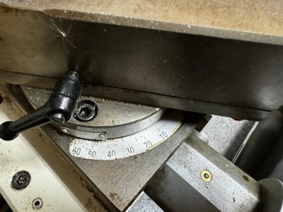
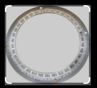
Grizzly doesn't list the index plate on the compound as a separate part, as far as I have been able to tell. In the manual, there are a few crudely-drawn lines indicating that an index plate goes vaguely in that area, but no part number is supplied, and I don't see a part that is an obvious match when browing the Grizzly web site.
The printing is coming off mine, and the adhesive holding it in place perished. I perhaps inadvisedly used contact cement to re-attach it; now I can't easily remove it to replace it. ☺
I'd rather have it engraved than printed on. Fill in the letters with black enamel, polish the surface, and suddenly it can survive normal use and be refurbished.
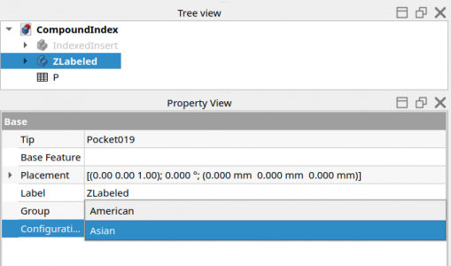
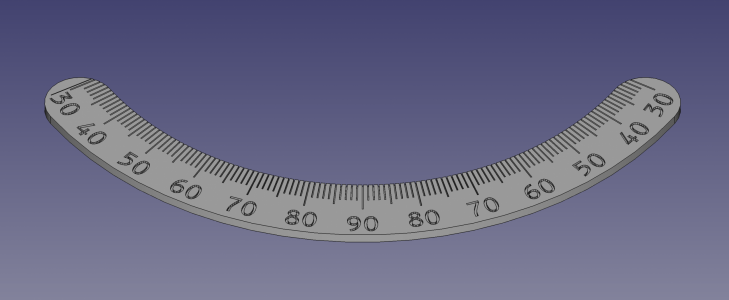
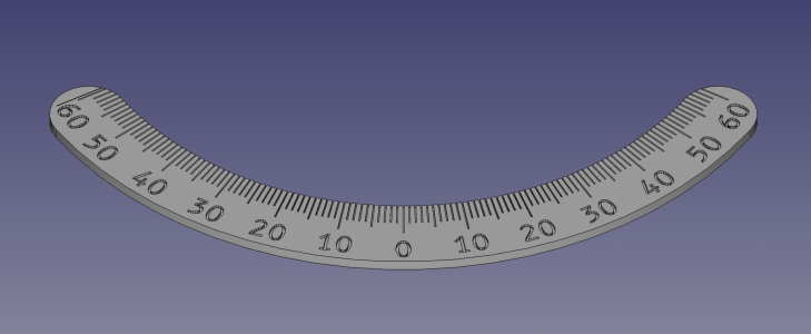
I tried to model it in FreeCAD. I don't know whether it will fit, and right now my CNC router isn't quite accurate enough, and my CNC mill has no control board in it at present, so I can't do a test run right now to find out if it's accurate enough. If anyone else needs one and has CNC handy, please feel free to try this and report how well it works. I have made it with the assumption that the engraving will be cut with a D-bit tool and then filled in, so instead of using a single-line font I used the B612 font developed by Airbus for high readability.
Because I sometimes accidentally use the wrong angle for single-point threading ("29.5°" got stuck in my brain, but asian lathes start from perpendicular to the Z axis instead of parallel to it) I modeled an additional light tick at 60.5° (29.5° from parallel) as a visible reminder.
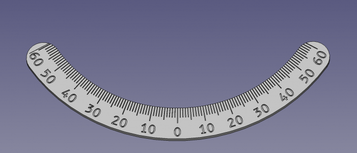
If anyone wants the other angle idsplay arrangement, it's just changing some strings in FreeCAD to get it labeled "30 - 40 - 50 - 60 - 70 - 80 - 90 - 80 - 70 - 60 - 50 - 40 - 30" — just a few minutes work.
Sadly, the step file and FCStd file are too large to upload here. But you can find them at https://gitlab.com/mcdanlj/G0709-compound-index-plate
If you try it out, please report whether or not it works. If it doesn't work I'd like to fix it. Sooner or later I do expect to make use of this! ☺
The printing is coming off mine, and the adhesive holding it in place perished. I perhaps inadvisedly used contact cement to re-attach it; now I can't easily remove it to replace it. ☺
I'd rather have it engraved than printed on. Fill in the letters with black enamel, polish the surface, and suddenly it can survive normal use and be refurbished.
I tried to model it in FreeCAD. I don't know whether it will fit, and right now my CNC router isn't quite accurate enough, and my CNC mill has no control board in it at present, so I can't do a test run right now to find out if it's accurate enough. If anyone else needs one and has CNC handy, please feel free to try this and report how well it works. I have made it with the assumption that the engraving will be cut with a D-bit tool and then filled in, so instead of using a single-line font I used the B612 font developed by Airbus for high readability.
Because I sometimes accidentally use the wrong angle for single-point threading ("29.5°" got stuck in my brain, but asian lathes start from perpendicular to the Z axis instead of parallel to it) I modeled an additional light tick at 60.5° (29.5° from parallel) as a visible reminder.

If anyone wants the other angle idsplay arrangement, it's just changing some strings in FreeCAD to get it labeled "30 - 40 - 50 - 60 - 70 - 80 - 90 - 80 - 70 - 60 - 50 - 40 - 30" — just a few minutes work.
Sadly, the step file and FCStd file are too large to upload here. But you can find them at https://gitlab.com/mcdanlj/G0709-compound-index-plate
If you try it out, please report whether or not it works. If it doesn't work I'd like to fix it. Sooner or later I do expect to make use of this! ☺

