Rebuilding/Refurbishing an Atlas Motor

louosten

Registered
Registered
Joined
Oct 11, 2013
Messages
90
Hello to All;

I am in the process of refurbishing an old Atlas 1/2 hp motor for a 10F lathe. It came off an Atlas band saw and was full of sawdust and old oil/grease. I can't get the case apart after removing the 4 steel rods holding the case together. Has anyone done this before, and will I damage the motor by disassembling it? It was tested beforehand and did run, although it was slow starting...I suspected that the starting capacitor would need replacing. Any suggestions would be appreciated.

Lou O.
 
Lou,

This usually works. You will need two 3/8" blade width screwdrivers, a 1" putty knife and a small (1# or so) shop hammer. If necessary, debur the output shaft so that it doesn't hang in or damage the bearing.

First, remove the line cord if still attached. Then, with a felt tip marker that makes visible marks on both the case and the bearing housings (invisible marks won't help), mark across each joint in a couple of places about 90 deg. apart so that you don't have to remember or figure out how it goes back together. Use one mark each place on the shaft end and two on the other. Rig up a stand out of scrap wood that will stand the motor up with the output shaft (assuming it's a single shaft) pointed up. Grind a 45 deg. bevel on the end of the putty knife blade, debur it, and use it with the hammer to split the bearing housing from the motor case. Then use the two screwdrivers in the gap thus exposed to lever the housing free and take it on off over the end of the shaft. You should now be able to pull the armature out of the motor. Make ID two marks across the switch end of the armature shaft with the felt marker.

Turn the motor over on the bench, so that the open end is down. If there is any wiring (terminal boards, etc.) attached to the remaining bearing housing, free it if you can so that it doesn't come up with the housing. Repeat the bearing housing removal procedure with putty knife and screwdrivers. Once free, lift the housing carefully to see what's still attached to it (probably the centrifugal switch, but it might be attached to the case) and if there is anything, disconnect it.

This should have the motor split into four major pieces.

Robert D.
 
Yesterday I just finished the rebuild of the 1/2HP unit that came with my 1950ish QC lathe. To get the unit seperated I used a large flat blade screwdriver placed on the lip of the front of the housing and hit it around the circumference with a dead blow. Once it is sperated enough I put a wedge in the gap and pried the front off (gently) with two flat blade screw drivers, just insert in the gap and twist the flat blade. Once the front is off the rotor will likely come with it. At that point you can tap the rotor out of the front of the housing. The rear bearing is likely still in the back of the housing, which I left on. To remove you need to hit it out with a pin inserted through a hole in the back. My motor already had a threaded hole for that very purpose. I replaced the bearings and start capacitor, cleaned up the start switch in the rear, replaced all of the wiring and put it all back together. The bearings I used were Nachi Sealed bearings, there is a guy on ebay that had them for several dollars each. Unit now fires right up and runs like a champ! Good luck!
 
Deburring the shaft(s) can be a bear if the motor doesn't run. You have the luck to have a running motor, so deburring is a piece of cake. Just start the motor and use a file to gently smooth the tops of the burrs off. When things seem pretty good, switch to some 120 grit sanding cloth, or a piece of 120 grit sandpaper looped around the shaft. Just hold the ends and LIGHTLY let it run up and down the shaft until it is uniformly smooth. When there are no "shadows" next to the edges of where the burrs used to be, you're done. Don't use the sandpaper any more than you need to or the shaft will be undersized. Take apart as indicated above. When I had to take a motor apart, I used a small chisel to make a permanent mark on the motor casing. I did this because when I painted it, a permanent marker would have been covered up. I used brake cleaner to get all of the dried grease and gunk off of the starter.
 
Last edited:
Every old motor I've taken apart and cleaned has been stuck shut. I found a lump of coal in a motor once, it was a Century centrifugal switch motor. Most likely a furnace blower motor, as that would explain the coal.
 
Thanks to all that posted instructions/advise on Atlas motor disassembly. It took me a while to get back to this project, but fortunately I was able to successfully get this motor apart.

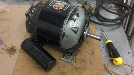
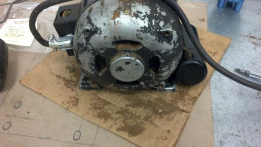
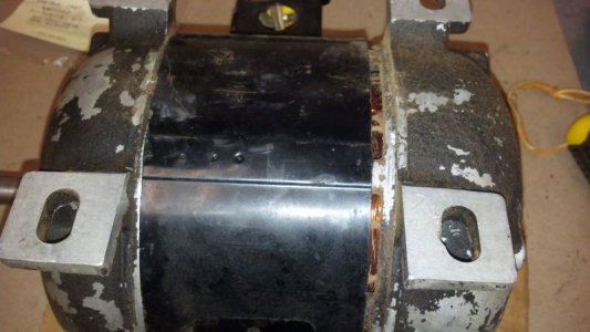
By carefully prying, the case began to open up:

Motor1.jpg

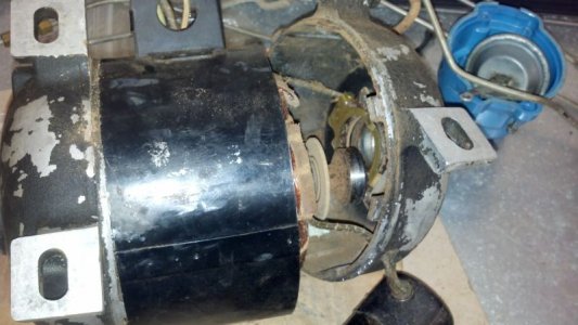
Continued work caused sawdust to fall out everywhere:
Motor2.jpg

The crack continues to widen:

Motor3.jpg

The bearing is finally freed from the case end:

Motor4.jpg

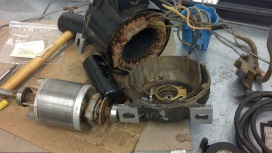
By tapping on the shaft end, the other bearing is freed The rotor is removed; note rubber mallet used in this operation:

Motor5.jpg

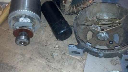
Better view of end bearing and centrifugal switch for motor start winding:

Motor6.jpg

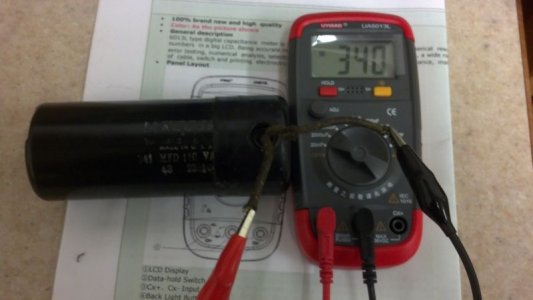
Testing Mallory 341 MFD capacitor yields good results:

Motor7.jpg

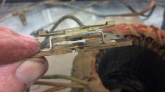
Starting problem was most likely dirty contacts on centrifugal switch:

Motor8.jpg

Both bearings will be replaced; the start capacitor checked out good, so I will re-use this part. Once re-assembled and painted, I'll post a final pic of a completed, running motor.

Lou O.

Motor1.jpg Motor2.jpg Motor3.jpg Motor4.jpg Motor5.jpg Motor6.jpg Motor7.jpg Motor8.jpg
 
Last edited:
I'd also renew the power cable there looks to be a weak bit / kink close to the motor housing . ( As in the second picture from the top )

One thing's for sure ..... if you don't renew it it's sods law that that is where the fault lies :lmao:
 
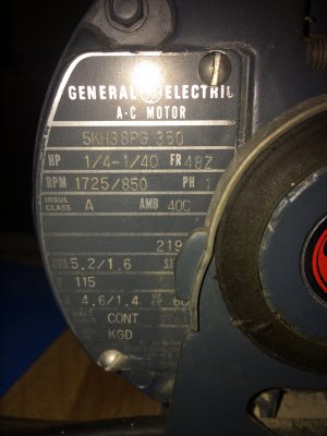
I am thinking about doing this to the old GE motor that I have slated to use for my 6" 101.21400 Craftsman / Atlas I noticed the other day that it is a 2 speed motor that could be wired to run at a lower speed and lower HP. It is a smooth running motor that came on a 1x42" belt sander that I bought at a yard sale for 10 bucks, to my un calibrated eye it appears to be running at 1750 but it could be running at the lower speed of 850 and 1/40 HP.
IMG_4134.JPG

IMG_4134.JPG
 
Well, it's time to finish up this project. I had to work on it part time so it took a little while to complete all the self-imposed tasks, since there wasn't a manual....

I got the old bearings off using a gear puller. It helps to heat them up a bit; I held the rotor over a kerosene stove to get the bearings hot to the touch.
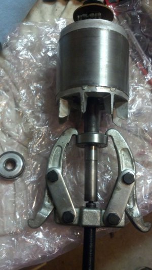
motor1a.jpg

I looked up the bearings and got two Nachi replacement bearings...both are different; the motor shaft end has the larger bearing.
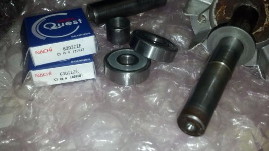
motor2a.jpg

To get the bearings on, I heated them both up (250 degrees F) in Wifey's oven (she was gone for the weekend).
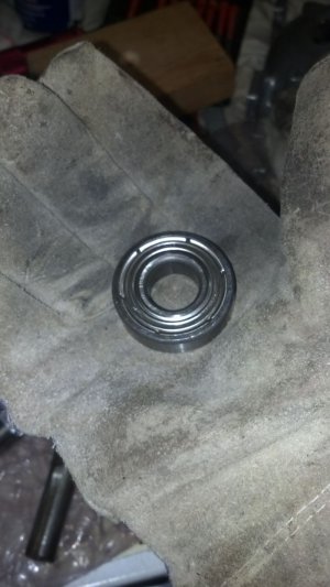
motor3a.jpg

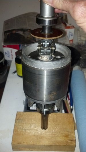
I didn't have a shop press, so I devised another way to get the bearings on without destroying them. I got a block of wood and drilled to receiving holes for the shaft ends.
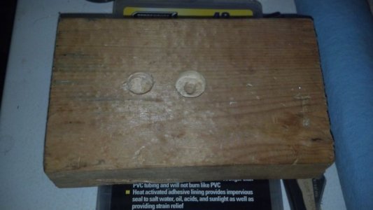
motor9a.jpg

Since the small end of the shaft didn't extend past the width of the bearing, I decided to put the larger bearing on first, then turn the rotor over and put the second one on. Once the bearings were heated up, I put a washer between them and a pipe/tubing sleeve; the end of the pipe and washer were covered with duct tape for cushioning.
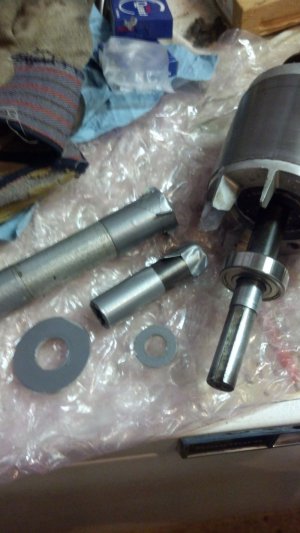

motor6a.jpg

Once everything was in place,

motor10a.jpg

I tapped the bearings home with light blows from a nostalgic hammer...
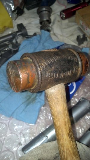
motor4a.jpg

After the bearings were on, I painted all the parts.
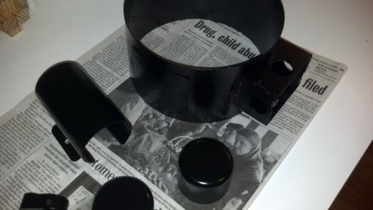
motor8a.jpg

The housing ends looked pretty good unpainted,
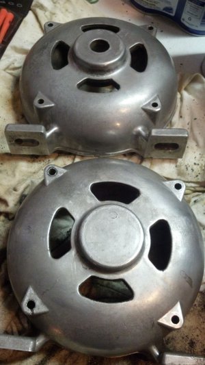
motor5a.jpg

but I thought the 'wrinkle effect' might keep the bearings cooler with the increased surface area, so I repainted them.
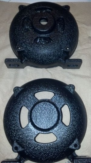
motor7a.jpg

Before reassembly, I checked the capacitor wiring...one side was loose and had to be re-soldered.
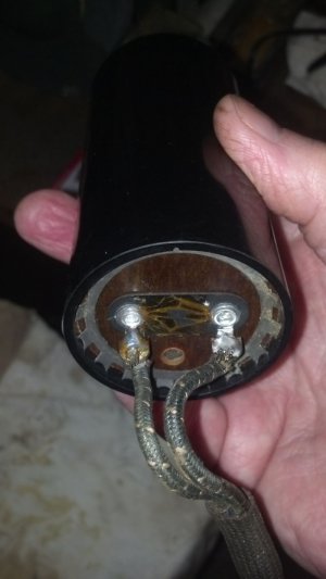
motor11a.jpg

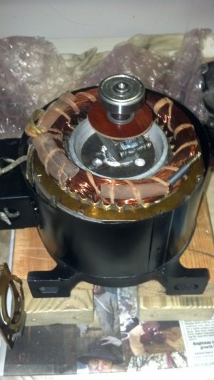
Reassembly goes easier by stacking components together in the vertical plane,
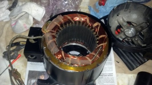
motor12a.jpg

It also helps to have some wood blocks to raise the housing for the motor shaft.
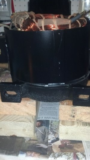
motor13a.jpg

Then the rotor goes in...

motor14a.jpg

At this point some wiring connections need to be re-made with the capacitor and centrifugal contactor. Once this is done, I put the other housing end on and tapped it home. The connecting rods then go in and get tightened. Once this is done, the motor is largely complete
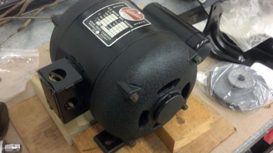
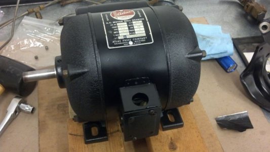
motor15a.jpg

motor16a.jpg

And now it's ready for the 'smoke test'...
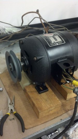
motor17a.jpg

The finished motor started and ran 'like a sewin' machine'....but backwards. Switching the two capacitor leads reversed the start direction. Now that this part of my lathe rebuild is complete, installation will have to wait until the rest of the machine is ready for power. Hope you enjoyed the adventure!

Lou O.

motor1a.jpg motor2a.jpg motor3a.jpg motor4a.jpg motor5a.jpg motor6a.jpg motor7a.jpg motor8a.jpg motor9a.jpg motor10a.jpg motor11a.jpg motor12a.jpg motor13a.jpg motor14a.jpg motor15a.jpg motor16a.jpg motor17a.jpg
 
thanks for a great walk through! I'm going to have to do this with a couple of lathe motors that don't start without a pull, so this has given me some great ideas of where to look.
 
Back
Top