Prime number division without gearing?

My version of PathPilot doesn't have a conversational program for bolt circles but I believe that the later versions do. If I recall correctly, Mach 3 had a wizard that did bolt circle patterns.

My Grizzly DRO has a bolt circle routine that would do a 127 hole pattern. Even though it is a manual operation, it is fairly well fool proof. You pick a hole and the DRO shows how far you are from the position. You just adjust the x and y axis for a 0,0 reading and drill. Hit the up or down arrow to go to the next hole.
 
............
Other than that, it would be a simple matter to create the model in SolidWorks or Fusion and let the CAM program write the code.
My brother said this is the way he would do it. He also said he had a macro somewhere in his stuff that could be used too. He mentioned the macro may not run on all brands or age of controllers.
 
I have a two axis BP CNC mill that will do this. One of the things that needs to be considered is the diameter of the dividing plate. For instance, if we assume a single row of .125 dia. holes on a 4.00" radius (approx. 8.25 dia. plate) it will leave about .073 of material between holes. If we assume a 3.00" radius (approx. 6.25 dia. plate) it will leave about .023 of material between holes and that's getting pretty thin.

Ted
 
guys, he has a 90:1 index head. the need is for 127 holes over 90 turns. To do this right, IMHO, the holes should be laid out in a spiral. if i were to do this, I'd use Excel, then print out the X Y values to a file. Do the work in polar coordinates, then convert to Cartesian.

Of course, may ways to skin the cat.

That would be kind of hard to index on when the spring plunger is on a fixed circle diameter.
 
guys, he has a 90:1 index head. the need is for 127 holes over 90 turns. To do this right, IMHO, the holes should be laid out in a spiral. if i were to do this, I'd use Excel, then print out the X Y values to a file. Do the work in polar coordinates, then convert to Cartesian.

Of course, may ways to skin the cat.
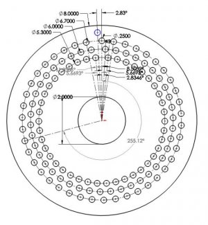
I laid out in SolidWorks a plate that should work. For a 90:1 head, the spacing would be 360 x 90/127 or 255.1181º. If that spacing is laid out with each successive hole being 255.12º from the last, you end up with 127 holes spaced at 360/127 or 2.8346º. The problem is that this spacing would result in intersecting holes.

126 is highly factorable; 2 x 3 x 3 x 7. What I did was break up the pattern into three sets of 42 holes spaced 3 x 2.8346 or 8.5039º apart and on radii. 35" apart Each set of holes was offset by the 255.12º This gave me 126 holes. The last hole was created at 2.8346º before the first hole, giving me the required 127 holes equally spaced in angle. My Grizzly DRO bolt circle function will easily make the hole pattern.

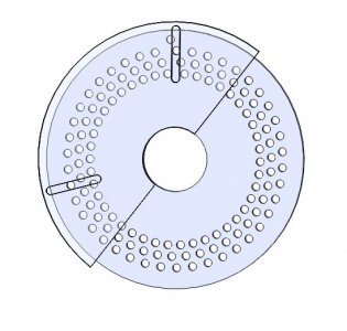
However, I can see that using the plate will present some problems.When a hole is made, the plate has to be rotated 255.12º or dropping down one circle and skipping to the 30th hole. This could quickly become confusing. To resolve that problem, I would make a template disk with two radial slots angled 255.12º apart and central pivot hole. When the hole was made, I would line up the slot with that hole which will expose the next hole to be made. The disk could be whole or a half disk as depicted to allow removal from the plate once a new hole was located.
127 Hole Index Plate Sketch.JPG 127 Hole Index Plate.JPG
 
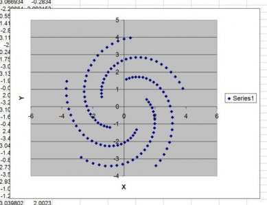
Just a concept here, using the spirial out idea. If you start at radius 1.5" and increase each point by 0.020, ending at radius 4.0, this is what the plate would look like. closest hole is 0.200 apart. Advantage here is not getting lost in your indexer. disadvantage is sliding the pin out 0.02 every move. Also make sure you can handle an 8" diameter. i could re do this with known min and max diametersCapture.JPG on the pin.
 
Just a concept here, using the spirial out idea. If you start at radius 1.5" and increase each point by 0.020, ending at radius 4.0, this is what the plate would look like. closest hole is 0.200 apart. Advantage here is not getting lost in your indexer. disadvantage is sliding the pin out 0.02 every move. Also make sure you can handle an 8" diameter. i could re do this with known min and max diametersView attachment 242862 on the pin.
Karl, if you start at the innermost hole on one spiral, your next hole has to be at 255.12º from the previous one (for 90:1 gearing). Which hole will that be on your plate?
 
Gentlemen,
I am truly quite ignorant when it comes to the complexities of dividing heads so if I'm not understanding something here I would appreciate a little education. It seems to me that in this particular case where we are dealing with a prime number that the easiest and simplest dividing plate would be one with a single row of 127 holes. I don't understand how the ratio of the dividing head even comes into play. It seems to me that the pin would just be advanced to the next hole on the plate in succession until all 127 equally spaced cuts had been performed. What am I missing ?

Thanks

Ted
 
With 90:1 gearing, the plate needs to rotate through 255.12º in order to turn the table 255.12/90 = 2.8346º = 360/127. Just moving to the next hole will only rotate the table by .0315º.
 
Back
Top