I have an early model PM 45 mill that has the manual hand crank for Z elevation. Since I just reorganized my shop and a toolbox is placed nearby, I'm going to attempt to convert it to powered elevation using a heavy duty gear motor that I've had for a long while.
I'm not 100% sure this will work to my satisfaction. The odds are maybe 70%... We'll see. I'll outline the design considerations as we go.
Here's some pictures and explanations...
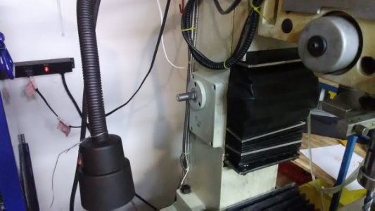
Here's the mill with crank handle removed. I put a wrench on the shaft flat and roughly measured the torque needed to raise the head. Holding the wrench about 1 foot (little less actually) from the point of rotation, I measured about 8-10 lbs to move it. This was measured by setting weights on the wrench which is a little inaccurate. Anyhow, I'm assuming it needs 10 ft.lbs to keep it in motion.
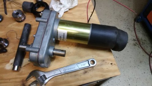
Here's a gear motor purchased at a surplus shop that I've had laying around for years. This motor is used in mobile-home campers to slide-out the extension walls and rooms from the sides of the campers. It's very heavy duty and purchased new, they cost over $300.
http://www.cshincorporated.com/rv-power-gear-slide-out-motor-pn-523900-k01531a300/
So... 400 in.lb is 33.33 ft.lb but, this is at 10 RPM. One full crank raises the head 1/8" so, it would take almost a minute to raise 1". -Too slow... Gears are needed!
With a 3:1 gear ratio, I'll only have 1/3 available torque, which happens to be 11.11 which is really darn close to the 10 ft.lbs I think is needed to move the head. With a 3:1 gear ratio, I'll get 30 RPM instead of 10. This means the head will raise 3.75 inches in 1 minute. That seems terrible but, it's not. Manually raising that head with the crank is a royal pain in the butt and is a very slow process. For the convenience of flicking a switch... I can live with slow.
A simple 2-gear solution immediately came to mind. For many, many years, I would dream-up ideas and just slap things together on the fly but not anymore. I no longer kludge things as I go. Time is too short and precious and I dislike getting 50% done only to find I'm boxed in a corner where my choices are ugly.
Here's a CAD model. The gear and shaft diameters truly represent the pitch circle. Given this, I can use CAD to take centerline measurements of the shafts and design an enclosure that will hold the gears at the correct spacing.
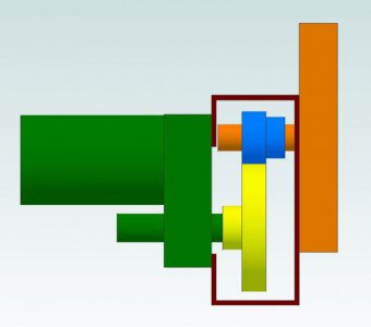
In the model, the gear sizes represent 85 and 35 teeth (respectively). This is a 2.43:1 ratio, not quite the 3:1 ratio I was thinking about before. This is because I'm using scrap pieces of metal for the gear blanks, using-up existing metal in the junk pile. 2.43:1 will be a little slower but, will give a little more torque.
So... Toss out questions, comments and suggestions. I'm going to dig-around the junk pile for more stuff and think this over before I start cutting gears.
Ray
I'm not 100% sure this will work to my satisfaction. The odds are maybe 70%... We'll see. I'll outline the design considerations as we go.
Here's some pictures and explanations...
Here's the mill with crank handle removed. I put a wrench on the shaft flat and roughly measured the torque needed to raise the head. Holding the wrench about 1 foot (little less actually) from the point of rotation, I measured about 8-10 lbs to move it. This was measured by setting weights on the wrench which is a little inaccurate. Anyhow, I'm assuming it needs 10 ft.lbs to keep it in motion.

Here's a gear motor purchased at a surplus shop that I've had laying around for years. This motor is used in mobile-home campers to slide-out the extension walls and rooms from the sides of the campers. It's very heavy duty and purchased new, they cost over $300.
http://www.cshincorporated.com/rv-power-gear-slide-out-motor-pn-523900-k01531a300/
- Speed 6 RPM @ 850 in-lbs, 25 Amps
- 10 RPM @ 400 in-lbs, 13 Amps
- 12 RPM (no load)
- Voltage 12 DC
- Torque 850 in-lbs
- Holding Torque 500 in-lbs.
- Rotation Reversible
- Duty Intermittent
- Enclosure TENV
- Mount Four bolt face mount on 3.38" x 3.38"centers
- Dual Shafts 3/4" diam. x 1-1/4" with 1/4" crosshole (no keyway)
- Size 9-1/4" x 3-7/8" x 6-1/4"

So... 400 in.lb is 33.33 ft.lb but, this is at 10 RPM. One full crank raises the head 1/8" so, it would take almost a minute to raise 1". -Too slow... Gears are needed!
With a 3:1 gear ratio, I'll only have 1/3 available torque, which happens to be 11.11 which is really darn close to the 10 ft.lbs I think is needed to move the head. With a 3:1 gear ratio, I'll get 30 RPM instead of 10. This means the head will raise 3.75 inches in 1 minute. That seems terrible but, it's not. Manually raising that head with the crank is a royal pain in the butt and is a very slow process. For the convenience of flicking a switch... I can live with slow.
A simple 2-gear solution immediately came to mind. For many, many years, I would dream-up ideas and just slap things together on the fly but not anymore. I no longer kludge things as I go. Time is too short and precious and I dislike getting 50% done only to find I'm boxed in a corner where my choices are ugly.
Here's a CAD model. The gear and shaft diameters truly represent the pitch circle. Given this, I can use CAD to take centerline measurements of the shafts and design an enclosure that will hold the gears at the correct spacing.

In the model, the gear sizes represent 85 and 35 teeth (respectively). This is a 2.43:1 ratio, not quite the 3:1 ratio I was thinking about before. This is because I'm using scrap pieces of metal for the gear blanks, using-up existing metal in the junk pile. 2.43:1 will be a little slower but, will give a little more torque.
So... Toss out questions, comments and suggestions. I'm going to dig-around the junk pile for more stuff and think this over before I start cutting gears.
Ray

