Power Z Conversion For PM45

I have an early model PM 45 mill that has the manual hand crank for Z elevation. Since I just reorganized my shop and a toolbox is placed nearby, I'm going to attempt to convert it to powered elevation using a heavy duty gear motor that I've had for a long while.

I'm not 100% sure this will work to my satisfaction. The odds are maybe 70%... We'll see. I'll outline the design considerations as we go.

Here's some pictures and explanations...

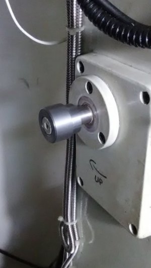
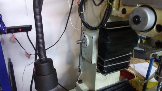
Here's the mill with crank handle removed. I put a wrench on the shaft flat and roughly measured the torque needed to raise the head. Holding the wrench about 1 foot (little less actually) from the point of rotation, I measured about 8-10 lbs to move it. This was measured by setting weights on the wrench which is a little inaccurate. Anyhow, I'm assuming it needs 10 ft.lbs to keep it in motion.
IMG_20180505_084318.jpg


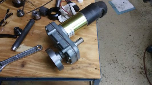
Here's a gear motor purchased at a surplus shop that I've had laying around for years. This motor is used in mobile-home campers to slide-out the extension walls and rooms from the sides of the campers. It's very heavy duty and purchased new, they cost over $300.

http://www.cshincorporated.com/rv-power-gear-slide-out-motor-pn-523900-k01531a300/
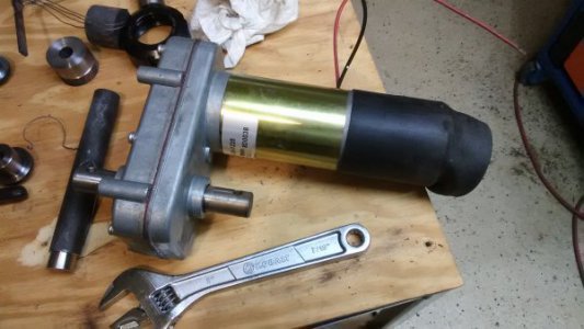
  • Speed 6 RPM @ 850 in-lbs, 25 Amps
  • 10 RPM @ 400 in-lbs, 13 Amps
  • 12 RPM (no load)
  • Voltage 12 DC
  • Torque 850 in-lbs
  • Holding Torque 500 in-lbs.
  • Rotation Reversible
  • Duty Intermittent
  • Enclosure TENV
  • Mount Four bolt face mount on 3.38" x 3.38"centers
  • Dual Shafts 3/4" diam. x 1-1/4" with 1/4" crosshole (no keyway)
  • Size 9-1/4" x 3-7/8" x 6-1/4"

IMG_20180505_100601.jpg

So... 400 in.lb is 33.33 ft.lb but, this is at 10 RPM. One full crank raises the head 1/8" so, it would take almost a minute to raise 1". -Too slow... Gears are needed!

With a 3:1 gear ratio, I'll only have 1/3 available torque, which happens to be 11.11 which is really darn close to the 10 ft.lbs I think is needed to move the head. With a 3:1 gear ratio, I'll get 30 RPM instead of 10. This means the head will raise 3.75 inches in 1 minute. That seems terrible but, it's not. Manually raising that head with the crank is a royal pain in the butt and is a very slow process. For the convenience of flicking a switch... I can live with slow.

A simple 2-gear solution immediately came to mind. For many, many years, I would dream-up ideas and just slap things together on the fly but not anymore. I no longer kludge things as I go. Time is too short and precious and I dislike getting 50% done only to find I'm boxed in a corner where my choices are ugly.

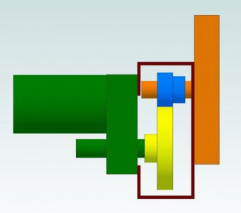
Here's a CAD model. The gear and shaft diameters truly represent the pitch circle. Given this, I can use CAD to take centerline measurements of the shafts and design an enclosure that will hold the gears at the correct spacing.
CrankMotorModel.JPG


In the model, the gear sizes represent 85 and 35 teeth (respectively). This is a 2.43:1 ratio, not quite the 3:1 ratio I was thinking about before. This is because I'm using scrap pieces of metal for the gear blanks, using-up existing metal in the junk pile. 2.43:1 will be a little slower but, will give a little more torque.

So... Toss out questions, comments and suggestions. I'm going to dig-around the junk pile for more stuff and think this over before I start cutting gears.

Ray
 
At the last minute, upon doing some time trials of how long it take me to manually crank the machine, I settled on gear ratios of 32 and 85.

Here are the blanks, I just finished them before posting.

I'm going to use some Modulus 1 gear cutters which are the closed size profile for what I feel will do the job. I have Mod 1, Mod 2 and DP 16 sized gear cutting sets. Given the overall size I want these gears to be and give the scrap pieces laying around, Mod 1 was the way to go.

Let me know if you want to see the calculations for the gear blanks and a refresher on tooth calculations.

The round collar is mainly cosmetic and just holds the bearing in place that supports the shaft. I'll remove the collar before attaching the motor unit.
IMG_20180505_124758.jpg

IMG_20180505_124836.jpg

Ray
 
I have an early model PM 45 mill that has the manual hand crank for Z elevation. Since I just reorganized my shop and a toolbox is placed nearby, I'm going to attempt to convert it to powered elevation using a heavy duty gear motor that I've had for a long while.

I'm not 100% sure this will work to my satisfaction. The odds are maybe 70%... We'll see. I'll outline the design considerations as we go.

Here's some pictures and explanations...

Here's the mill with crank handle removed. I put a wrench on the shaft flat and roughly measured the torque needed to raise the head. Holding the wrench about 1 foot (little less actually) from the point of rotation, I measured about 8-10 lbs to move it. This was measured by setting weights on the wrench which is a little inaccurate. Anyhow, I'm assuming it needs 10 ft.lbs to keep it in motion.

View attachment 266844


Here's a gear motor purchased at a surplus shop that I've had laying around for years. This motor is used in mobile-home campers to slide-out the extension walls and rooms from the sides of the campers. It's very heavy duty and purchased new, they cost over $300.

http://www.cshincorporated.com/rv-power-gear-slide-out-motor-pn-523900-k01531a300/
  • Speed 6 RPM @ 850 in-lbs, 25 Amps
  • 10 RPM @ 400 in-lbs, 13 Amps
  • 12 RPM (no load)
  • Voltage 12 DC
  • Torque 850 in-lbs
  • Holding Torque 500 in-lbs.
  • Rotation Reversible
  • Duty Intermittent
  • Enclosure TENV
  • Mount Four bolt face mount on 3.38" x 3.38"centers
  • Dual Shafts 3/4" diam. x 1-1/4" with 1/4" crosshole (no keyway)
  • Size 9-1/4" x 3-7/8" x 6-1/4"

View attachment 266845

So... 400 in.lb is 33.33 ft.lb but, this is at 10 RPM. One full crank raises the head 1/8" so, it would take almost a minute to raise 1". -Too slow... Gears are needed!

With a 3:1 gear ratio, I'll only have 1/3 available torque, which happens to be 11.11 which is really darn close to the 10 ft.lbs I think is needed to move the head. With a 3:1 gear ratio, I'll get 30 RPM instead of 10. This means the head will raise 3.75 inches in 1 minute. That seems terrible but, it's not. Manually raising that head with the crank is a royal pain in the butt and is a very slow process. For the convenience of flicking a switch... I can live with slow.

A simple 2-gear solution immediately came to mind. For many, many years, I would dream-up ideas and just slap things together on the fly but not anymore. I no longer kludge things as I go. Time is too short and precious and I dislike getting 50% done only to find I'm boxed in a corner where my choices are ugly.

Here's a CAD model. The gear and shaft diameters truly represent the pitch circle. Given this, I can use CAD to take centerline measurements of the shafts and design an enclosure that will hold the gears at the correct spacing.

View attachment 266850


In the model, the gear sizes represent 85 and 35 teeth (respectively). This is a 2.43:1 ratio, not quite the 3:1 ratio I was thinking about before. This is because I'm using scrap pieces of metal for the gear blanks, using-up existing metal in the junk pile. 2.43:1 will be a little slower but, will give a little more torque.

So... Toss out questions, comments and suggestions. I'm going to dig-around the junk pile for more stuff and think this over before I start cutting gears.

Ray

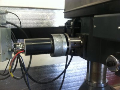
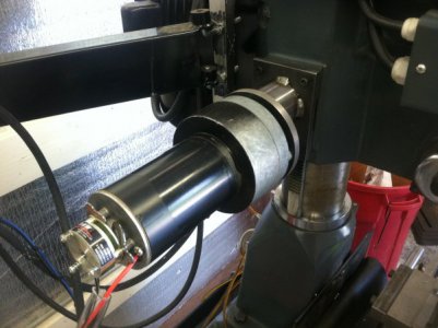
You are on the right track using an RV slideout motor. I did the same on my RF-30 mill a couple of years ago. These motors can move a slideout that weighs several hundred pounds so raising a milling machine head should be easy.

Here's a couple of pictures of my setup.

IMG_0300.JPG

IMG_0301.JPG
 
You are on the right track using an RV slideout motor. I did the same on my RF-30 mill a couple of years ago. These motors can move a slideout that weighs several hundred pounds so raising a milling machine head should be easy.

Here's a couple of pictures of my setup.

View attachment 266897

View attachment 266898

Thanks... That's a good data point to be aware of. The model of gear motor I have seems to be common and the specs are impressive but still, there's always an element of surprise when you first slap something together.

Ray
 
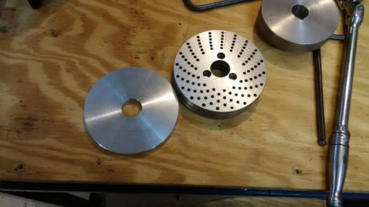
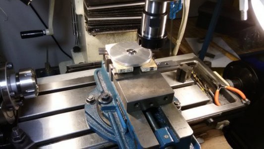
We have a little detour due to a surprise when cutting the gears. Actually, I got a double-whammy... For the gear teeth sizes I chose, one of them can't be cut with a 90:1 rotary table. 85 is not possible so I decided to go with 80 teeth because it needed the same hole-plate as the mating 32 tooth gear. -And of course, I either did not have, or cannot find, the plate with 64 holes which is needed for the 32 and 80 tooth gear.

So... How do you fix that?

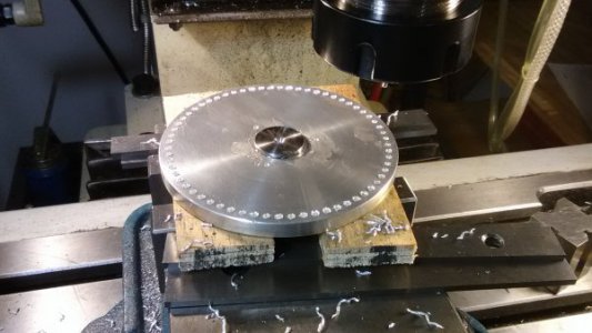
Behold... 64 evenly spaced holes.
IMG_20180506_185312.jpg IMG_20180506_220854.jpg IMG_20180507_180146.jpg

Almost done. I need to drill the 3 holes in the middle. Later on when this project is over, I'll drill the other hole sets that belong on that plate. I think 62, 54 and 50 are missing. I'l get e'm all on there sooner or later even if I have to stagger them.

When I finish the 64 hole plate after dinner, I'll come-back and do a write-up of gear calculations and gear cutting.

Ray
 
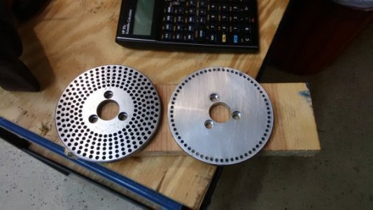
This came out nicely and it fits/works perfectly on the rotary table. Those 64 holes was a minor pain in the butt. All total, it took 2 hour to drill them. Would be a perfect job for CNC. I made 2 passes. Spot-drill followed by the drill. I took my time and approached each hole position with the same approach on the wheels. If I accidentally overshot, I would back up a good amount and re-approach always turning the hand wheels in the same direction for every hole. Doing this seems like overkill but, from past experience, I've learned this technique is effective when looking to drop multiple holes from a common datum.

It paid off. Using a couple pin gages, the hole spacing was spot checked in about 15 places and everything came-out surprisingly uniform. The variance on the factory plate was about the same as the new one.

IMG_20180507_210553.jpg

Ray
 
I wanted to get one of those motors back when surplus center had them, but I snoozed and lost out.
 
OK, gears are made (see link here: https://www.hobby-machinist.com/threads/cutting-gears-diametral.69653/#post-583860) so this motor attachment project can move on.

No big deal here, just cut a keyway into the gear motor shaft.
IMG_20180512_153852.jpg

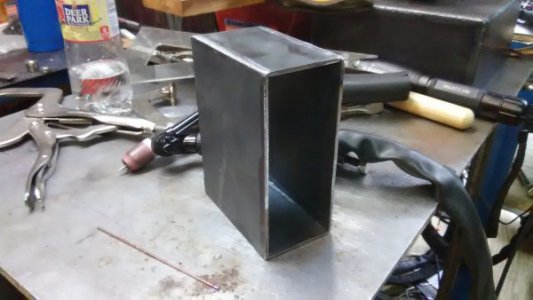
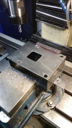
Make a box to hold the gears. This 11 ga (.120") hot rolled. It was TIG'd together then rounded off. If this works I'll build side covers for it and paint it too.
IMG_20180512_191725.jpg

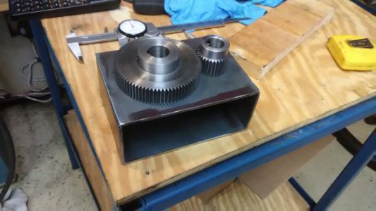
Preliminary layout of gears as a sanity check.
IMG_20180512_191959.jpg

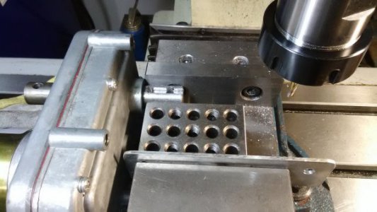
Drop some holes as per the model.
IMG_20180512_204022.jpg

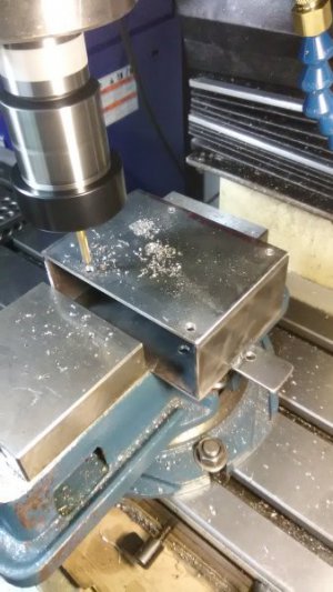
...and drop more holes. These are elongated so the motor can be positioned with the correct gear engagement.
IMG_20180512_210822.jpg

And so far, it looks like everything is lining up OK. I still need to drill/tap into that heavy plate. There are 3 holes around the shaft at the top but, they're only 4 or 5mm. There's going to be a lot torque placed on them so I want at least 1 more at the bottom. Also, I screwed-up and made the box too small. The plan called for it to be 6" x 4" x 2.4" and for whatever reason in the universe, I made it 5" x 4" x 2.4". That's why I welded a tab on the top. It's good enough and I'm not going to mess with it. It will serve as a constant reminder not to make stupid mistakes.
IMG_20180512_211904.jpg

None of the screws are tight but things will line-up nicely when everything is snugged-up.
IMG_20180512_212024.jpg

Almost there... We'll be testing this tomorrow if all goes well.

Ray
 
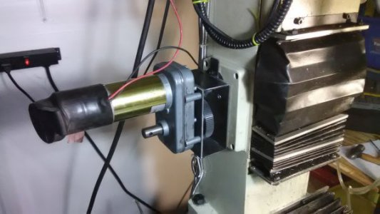
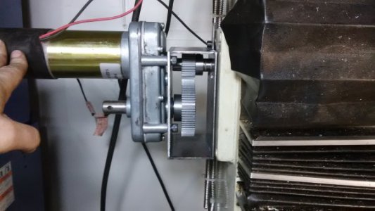
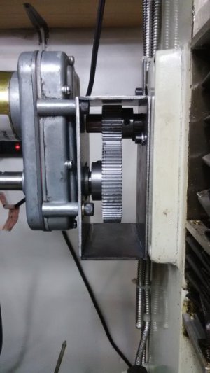
FYI: After making shaft keys, getting everything aligned, bolts tightened and test-run with an automotive battery charger...

There's no flexing in the housing, the shafts are not splaying under torque and the motor does not seem to be straining. Best of all, the travel speed is about identical to what I can do cranking it manually. I ran it the full travel up & down twice in a row (a very uncommon scenario) and the motor warmed-up only a few degrees over room temperature.

So far, so good -and I should have done this about 6-7 years ago when I bought this mill.

The project is not over... The search is on for a dedicated 12v power supply that can source about 20 amps. Then of course, finishing it off with full enclosure, paint, reversing switch etc..

BTW: No, the box is not crooked... The cheap phone camera gives fish-eye lens distortion to anything close-up.

IMG_20180513_083502.jpg

Ray
 
Looking good! Thanks also for the gear cutting lesson which sure seemed to shed some light on that topic for me at least. :encourage:
 
Back
Top