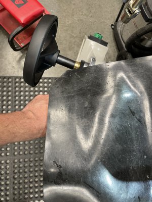
Power knee feed for FTV-1

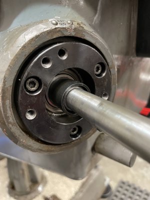
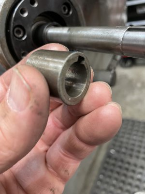
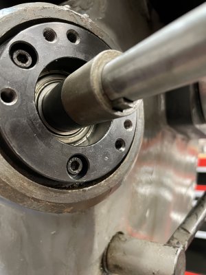
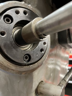
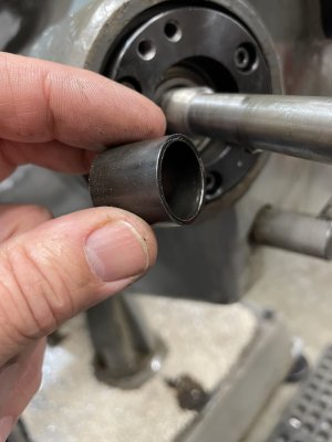
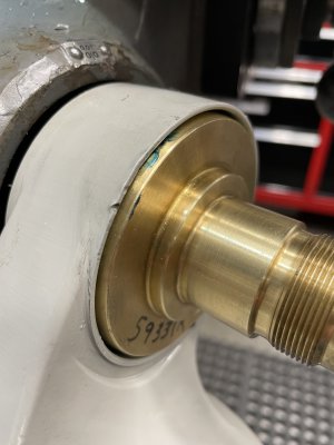
With the jackshaft back in the knee, use the supplied bearing retainer, rather that the factory unit, and tighten it down. Install the spacer #6740 and the bearing race from the Lagun kit. It's not very clear which one either of these is ( Thanks to Jon/H&W for clearing this up! ). Here is a photo of each, and where they go.

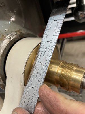
First "spacer #6740". It basically covers the threaded area of the jack shaft, and ultimately transfers the load to the inner bearing race.
IMG_8558.JPG
IMG_8559.JPG

Followed by the "bearing race"
IMG_8560.JPG
IMG_8561.JPG
 
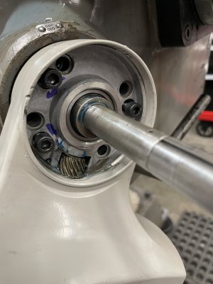
Slide the drive onto the bearing race, and tip it out to allow access to your knee lock handle, and pick out three holes that are over virgin material on the bearing retainer and use a transfer punch to locate the holes. Remove the bearing retainer, drill and tap the three punch marks to 1/4"-20 and install the bearing retainer for good this time. You'll also want to make sure the woodruff key is now in place, as it will locate both the bearing race, and the upcoming bevel gear.

These three cap screws are the holes I used to mount the drive to the bearing retainer.
IMG_8562.JPG
IMG_8561.JPG
 
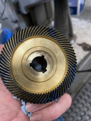
Now, it's time to mount the drive to the three holes you just drilled and tapped, and test fit the bevel gear. The largest of the three key slots in the bevel gear will share half of the woodruff key in the bearing race.
IMG_8563.JPG

Be certain that the bevel gear seats completely. You have a couple chances at a "false bottom" First, when it's not yet on the woodruff key, and again when its on the key, but the gears haven't meshed. Here's what it looks like on a false bottom. The gear will still be proud oof the drive housing.
IMG_8564.JPG

Once it's fully seated, it should be below flush from the rim of the drive housing by .080"-.085". Use shims to set this depth. Even though they showed shims with woodruff slots already in them, none of mine were, so you'll have to notch them yourself.
IMG_8567.JPG
 
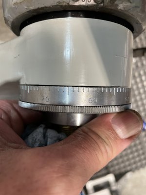
Then comes the dial. You'll need to shim it until there is a .005" gap between the dial and the bevel gear, to keep chips out as much as possible.
IMG_8568.JPG
 
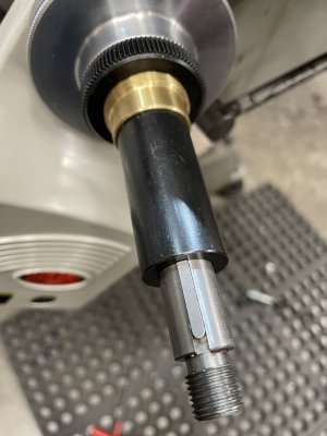
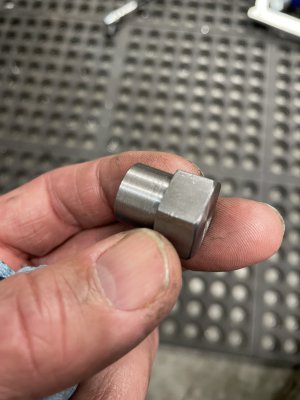
Almost there. Slide the long spacer on, and butt up against the end of the bevel gear. Cut a piece of key stock to fill the slot from the end of the spacer, to the end of the shaft extension, and slide the hand wheel on. If you're lucky, you'll have the special 1/2"-20 nut to retain the hand wheel, and load the bearing. If not, you'll have to make one. I just used some 3/4" hex stock, and turned it.
IMG_8569.JPG
IMG_8570.JPG
IMG_8572.JPG
 
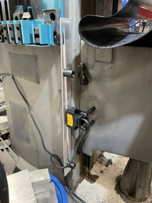
Last thing is to install the limit stop switch. Here I hit another snag. The first was that I thought the track to hold the sliding stop bumpers was kind of a cheap flimsy POS. So, I made one out of some aluminum angle I had on hand, and slotted it with a 3/8" end mill, once I established the slope needed to make up for the tapered side of the mill column. Yes I could have just shimmed it plumb, but chose to do it this way, cause I felt like it. Got it mounted and lined up, only to discover that the microswitches were either wired backwards, or installed in the wrong order! Basically, the the knee was traveling up, pressing the bottom switch stopped it, and vice versa going down. Popped the cover off, swapped the microswitches, and it's finally done!
IMG_8573.JPG

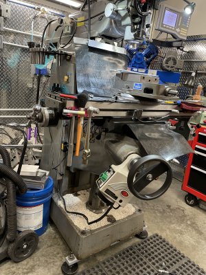
I initially thought that the hand wheel would be sticking out too far, and I was going to shorten the shaft. Glad I didn't. It only sticks out slightly more than the Y axis crank at it's mid travel, and it provides plenty of room for you knuckles when cranking the Y axis. Now that it's all sorted out, I love it. What a luxury! Thanks for enduring the wordy, picture heavy rambling?
IMG_8575.JPG
 
Nice work! I need to do some power feeds on my Lagun.
 
Back
Top