Potentiometer causes motor drive erratic behavior, but only when mounted/grounded

FliesLikeABrick

Wastestream salvage addict
H-M Lifetime Diamond Member
Joined
Oct 30, 2019
Messages
225
Hi all, this is an area where I am normally in my comfort zone but this issue is odd enough that I have run out of ideas and ruled out the causes that make sense to me. Take any of my reasoning, editorializing, leaps or conclusions below with a grain of salt, since I clearly am missing something and not capable of solving/fixing this problem yet.

I just finished setting up a new drive for my Bridgeport's 6F x-axis powerfeed, using a Minarik drive and the guidance provided at https://www.atechfabrication.com/information/Bridgeport_Feed_Controller.htm

All looked and worked great, so I buttoned up the enclosures and mounted everything back together.

When testing again after fully mechanical assembly, I found the following symptom:
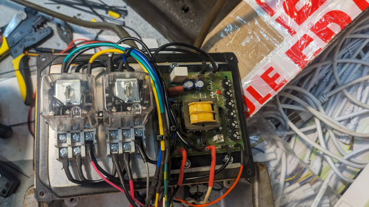
  • Instead of soft starting, the motor would "bump" a bit, stop, then slow-start. The drive appears to otherwise operate normally
  • This symptom would only happen when the 10k (linear taper, 2 watt) potentiometer was mounted in the panel, and the panel mounted in the motor housing (which is grounded along with the rest of the machine)
  • If the potentiometer or panel were floating free in space, everything behaves 100% normally
  • One time while testing it (perhaps at higher speed), it actually tripped the GFCI breaker for the circuit in the shop that this is plugged into
  • I measure maybe 60 vollts DC (the relay coils and field windings happen to be 110VDC) from the pot to ground when it is floating, but very very low current - like 5 microamps. The potentiometer itself is only fed ~.7 vdc
  • One time I was touching the pot with my hand and my nose brushed against something on the head of the mill, and I felt what felt like a static shock. This seems to align with a very small leakage current building up a charge on the potentiometer that is discharging. I did not care to reproduce this observation/symptom
  • The control panel has a button for rapid traverse, but no leads are currently connected to it, so only the potentiometer seems to be in-scope
1694445561090.png
I have a demonstration and explanation of the issue in the video below:

Troubleshooting I've done so far:
  • Tested the potentiometer for leakage paths from the resistive element and wiper to its case/ground and found nothing, all open (tested with a ~20 megohm DMM)
  • Replaced the potentiometer with an identical one (I bought two at the same time); same behavior
  • Verified that none of the control wiring between the drive housing and the motor has a short to ground. This wouldn't really make sense anyway, since it very clearly is only happening when the metal pot housing is grounded, meaning the wiring should be excluded
  • Per recommendations in the Minarik drive's manual, I twisted the potentiometer wiring (S1,S2,S3 in the diagram linked above) together
  • I also added an extra ground jumper from an unpainted portion of the drive's board straight to the ground lug on the enclosure, in case the paint plus rubber seal on the back panel were not allowing a clear enough path
Other steps I am thinking about taking:
  • Replacing the pot with a different make/model from a different manufacturer, just in case it is something subtle about its electrical characteristics that are causing this. The current potentiometer is a Centralab RV4NAYSD103A
  • Running a separate 3-lead conductor from the motor/controls housing back to the drive enclosure, in case something is picking up interference from the power conductors in the OEM cable assembly. I would be surprised if this was the case, since I can't come up with an explanation for why this would only be the issue when the pot case is grounded.

Thanks for any guidance or brainstorming that might be offered
 
Last edited:
Makes me think of a ground loop. Possibly a poor ground connection somewhere in the controls that is finding a path through that plate. Possibly floating the "ground" in the circuit somewhere to the 60VDC you saw earlier. It's a bit of a shot in the dark, but the symptoms from the times I've fixed one are always a bit bizzare.
 
Makes me think of a ground loop. Possibly a poor ground connection somewhere in the controls that is finding a path through that plate. Possibly floating the "ground" in the circuit somewhere to the 60VDC you saw earlier. It's a bit of a shot in the dark, but the symptoms from the times I've fixed one are always a bit bizzare.
I was thinking something similar, and did add an extra ground jumper from the drive board to the chassis/power ground point just to be sure (no improvement).

The other issue with this theory ("something is floating that the potentiometer is grounding", that I kept coming back to myself) is that the potentiometer has no ground conductor going to it, and the metal case should be 100% isolated (and measures via DMM as such) from the 3 leads that do go to it -- so it shouldn't be capable of grounding something that is otherwise floating. It was only floating when I let it float.

That said, the fact that the floating potentiometer might have 60VDC on it would indicate that these pots are indeed leaking current, so I'll try a different make/model of pot or just replace it with a voltage divider of resistors and see what happens. The pot must be leaking current with a resistance that the DMM can't measure at its test voltage, but at ~100VDC it is able to overcome whatever isolation there is somewhere in the leakage path within the pot. That is my best theory currently...
 
Last edited:
I was thinking something similar, and did add an extra ground jumper from the drive board to the chassis/power ground point just to be sure (no improvement).

The other issue with this theory ("something is floating that the potentiometer is grounding", that I kept coming back to myself) is that the potentiometer has no ground conductor going to it, and the metal case should be 100% isolated (and measures via DMM as such) from the 3 leads that do go to it -- so it shouldn't be capable of grounding something that is otherwise floating. It was only floating when I let it float.

That said, the fact that the floating potentiometer might have 60VDC on it would indicate that these pots are indeed leaking current, so I'll try a different make/model of pot or just replace it with a voltage divider of resistors and see what happens. The pot must be leaking current with a resistance that the DMM can't measure at its test voltage, but at ~100VDC it is able to overcome whatever isolation there is somewhere in the leakage path within the pot. That is my best theory currently...
I think you are on the right path. It is unlikely that the potentiometer is rated for 60v. Is the circuit supposed to apply that much voltage to the pot?
 
After reading your post, I'm wondering if there might be some sort of capacitive effect going on.
If it's operated by high speed pulsing which could act like radio frequencies which are affected
that way. If the manual mentions twisting the wires, it sort of adds up. You might try running
the wires through a ferrite core and see if that would fix it.

Another thing one could do would be to make a non conductive front plate.
 
I think you are on the right path. It is unlikely that the potentiometer is rated for 60v. Is the circuit supposed to apply that much voltage to the pot?
thanks I just double-checked - S1 to S3 (the voltage range given to the pot) is only .7vdc across the resistive element. However, that is not ground-referenced so it is about 50VDC off of ground on both ends of the resistive elemtn. The potentiometer is rated for 500v, so isolating a high-impedence 50V from ground should not be an issue.

The manual specifies that grounding the potentiometer leads can cause damage, so the fact that its voltage is not ground-referenced makes sense. However, that doesn't mean it should be energizing the case of the potentiometer. I am increasingly optimistic that a different potentiometer (different make/model) may change the shape of this problem.


After reading your post, I'm wondering if there might be some sort of capacitive effect going on.
If it's operated by high speed pulsing which could act like radio frequencies which are affected
that way. If the manual mentions twisting the wires, it sort of adds up. You might try running
the wires through a ferrite core and see if that would fix it.

Another thing one could do would be to make a non conductive front plate.
Thanks I have a bunch of clip-on ferrite cores salvaged from something else, will try that.
 
Last edited:
Thanks I have a bunch of clip-on ferrite cores salvaged from something else, will try that.
Sorry for replying to myself so quickly (I am antsy to test all the theories on this and keep moving to solve it) -- I clipped a core on the 3x pot wires twisted together as well as one on the S2 speed sensor input -- no change.

I am editing my original comment to clarify my comments about the controls being 100VDC
 
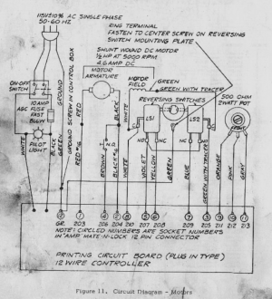
Reading along and looking at the circuit diagrams, I noticed the diagram specifies a 500 ohm 2 watt pot
and you make mention of a 10K pot. There is probably good reason for this but am trying to be helpful
so decided to mention it.
 
No no no, it's not a ground loop- the drive is not transformer-isolated from the line- the pot may need to be isolated from the chassis
KB drives are the same way
They usually provide a pot with a nylon shaft and insulating plastic washers to accomplish the isolation
The pot probably has some leakage to ground- it shouldn't but it might so with 50 volts on it you can't ground it or let it leak to ground

If the Minarik has full isolation between the high and low power sections then it shouldn't matter but I don't know how they
deal with the isolation scenario exactly
 
Last edited:
Reading along and looking at the circuit diagrams, I noticed the diagram specifies a 500 ohm 2 watt pot
and you make mention of a 10K pot. There is probably good reason for this but am trying to be helpful
so decided to mention it.
Great question -- if you are referring to this diagram, it is the original Bridgeport 6F drive:
1694456815670.png

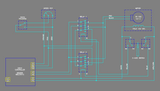
The replacement diagram with the Minarik drive is this, below.
1694456842554.png

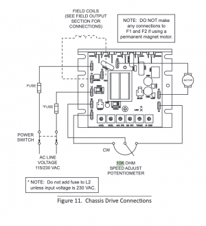
The Minarik drives use a 10k pot, from the manual:
1694457377323.png

I appreciate that you are looking into it in this detail, thank you.
 
Last edited:
Back
Top