DRO installation continued:
X, Y and Z all done and functional, but I have the display for 4th axis (U) and the scales for the quill. Hmmm, how to mount it?
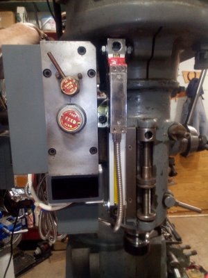
This is on an old South Bend Mill with the power down feed accessory for the quill. There are 4 bolts that clamp the head to the ram and they are held on with T-studs and internal 12 point nuts. The addition of the power down feed makes access to the nuts troublesome enough that SB actually made a special wrench just for this.
The logical location for the scales would cover up one of the nuts.
A friend was over the other day and we were discussing options. His suggestion was to mount the scales in the preferred location, but make them easily removable so that I could get to the "hidden" nut. I thought this was an excellent idea and decided to take a look at it today.
I pulled up the parts diagram and determined that there were lots of option for drilling and tapping into the power down feed structure. While trying to decide the best approach, something occurred to me. IF I positioned the scales exactly right, they would leave clearance to get a long 3/8" hex wrench into the "hidden" nut. Hmmmmm!
Even after drilling and tapping several holes in my mill, I still have and aversion to defacing old iron any more than necessary.
Looking around for mounting options I came up with an idea or two.
First up, the clamp that holds the motor mount onto the head is a cap screw and the threads are on the left side of the slot (where I want to mount the scales). The cap screw takes up all the depth of the casting. I removed the cap screw and verified that the casting is threaded all the way through on the left of the slot. There were lots of threads in the casting. I found a replacement cap screw that was a little shorter than the original. Installed that and it clamped fine.
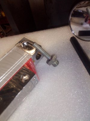
Then found a short 3/8" bolt and shortened it even more in the lathe so that there were just enough threads that it would hold well in the casting. Then drill the center and tapped it for a 1/4" stud. Measured and cut the stud, using thread locker to secure it to the bolt.
Milled out the mounting slots of the scales to 1/4" (no metric fittings on my old American machine!) It was a bit of a trick getting it all threaded into place given the confined space. Made a 1/2 thick nut in the lathe for alignment adjustments.
OK, top mount done, now what about the bottom?
There was a graduated scale mounted to the head for use with the depth stop on the quill. As it was from the factory, the scale was not aligned exactly with the outside radius of the depth stop nut. I removed the scale and made an aluminum angle to mount under the scale with slots for the screw for alignment. This was 1/16" thick angle and it actually improved the readability of the scale. AND the factory mounting screws were long enough to still be used. A hole in the side and a 1/4" bolt and nut provided a nice solid bottom mount point.
The best part is, the "hidden" nut is still accessible. The scale is in the preferred location and permanently mounted.
All that is left is to figure out the mount between the quill and the sliding read head of the scales. That will be POT (Project of Tomorrow)
Thanks for reading.
 Been a long day but knocking it out .
 Been a long day but knocking it out .


