PM932 CNC Build

Jay,

After extending the Y axis notch and removing the bellows how much total travel did you end up with?

Tom S

Y-axis now has 9.8" of travel (without any way cover). I could have gone a little more but I am limited by the enclosure and chip tray. The mount for the rubber way cover takes away an inch so I have 8.8" of usable travel.

Jay
 
Y-axis now has 9.8" of travel (without any way cover). I could have gone a little more but I am limited by the enclosure and chip tray. The mount for the rubber way cover takes away an inch so I have 8.8" of usable travel.

Jay

Thanks for the info. I did the slot extension mod also and got about 10 inches but with the way cover installed. Heard/read where someone got about 12 inches of Y travel. Not sure if the way cover was still used and how much overhang on the saddle but 12" seems excessive.

Tom S
 
View media item 94569
Thanks for the info. I did the slot extension mod also and got about 10 inches but with the way cover installed. Heard/read where someone got about 12 inches of Y travel. Not sure if the way cover was still used and how much overhang on the saddle but 12" seems excessive.

Tom S

12" of travel without any way covers would have more than half the saddle hanging off the base, about 5". I would not go over 1/3 overhang.
 
The thread I was referring to is written by GT40 and is on this forum. He did a few things differently that what I've done and was able to get a shade over 11" with the bellows installed.

And I agree with you on saddle overhang. My max out travel puts me at 3-3/16" overhang which is 1/3 of the saddle front to back measurement.

Tom S
 
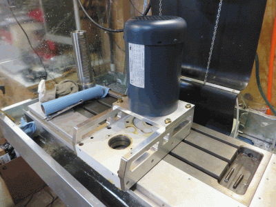
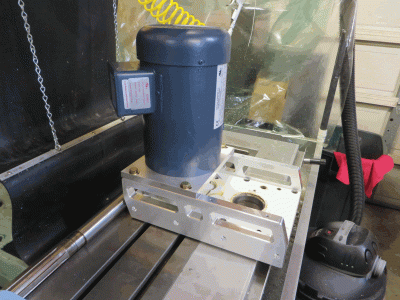
Finally got started on the VSD conversion. I milled the motor mount parts before tearing the head apart. The new electronics ran great with no drama. It's always nerve wracking to run new programs after making modifications. I'm always afraid I missed something. The motor is a 2hp 3ph inverter duty. It was gifted to me by a friend and also came with a Haunyang 3hp VFD. He bought it for a project but decided to upgrade before using it. I'm not super thrilled about having to setup the Chinese VFD as my first VFD but the price was right. Hopefully someone here can walk me through it. The manual is a nightmare to read.

pm932_VSD_mount_01.gif pm932_VSD_mount_02.gif

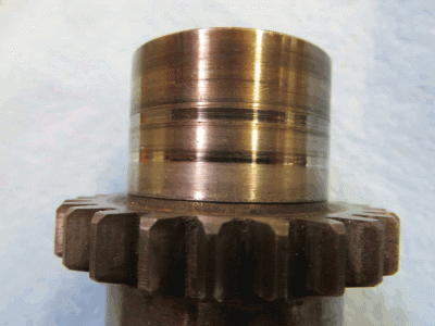
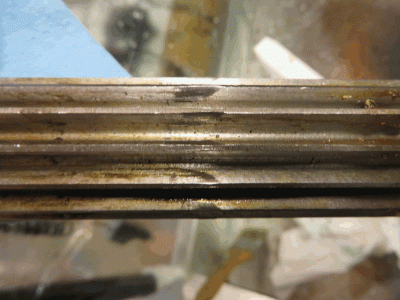
Tore down the gear head and removed the spindle. I had taken the cover off about 3 months after getting the mill to install the pneumatic drawbar and at that time the gear oil looked good so I left it alone. A year later the oil is almost black and smells burnt. After draining the oil and cleaning out the head with solvent I found lots of casting grit in the bottom. The splined shaft that drives the spindle has score marks where it rubs against the seal. I think this is where the oil was leaking from. It is hard to tell in the photos but the polished areas are about 0.006" deep

pm932_splined_shaft.gif

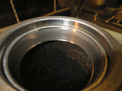
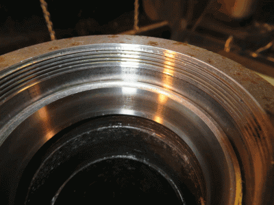
Another item of concern I found was the condition of the spindle bearings.

Upper bearing race.
pm932_upper_spindle_bearing.gif

Lower bearing race.
pm932_lower_spindle_bearing.gif

and lastly, the quill pinion was not orientated well with the rack gear on the back of the quill body causing wear marks on the pinion gear. The quill has hardly been used.

pm932_quill_pinion.gif

My original plan was to maintain the quill travel but after getting more comfortable with the CNC machining I see no reason to keep that on so I now plan on fixing the quill in place. I'm curious how others have done this? I'm not sure I would trust the quill lock alone???

Next step is to get the bearing races out of the spindle housing and install the AC bearings. The upper should'nt be too bad but I'm not sure how I'm going to get the lower bearing out as the is very little room to catch and edge for pressing and the center bore is smaller than the bearing race so access is limited. I'm open for suggestions on what others have done?

Jay
 
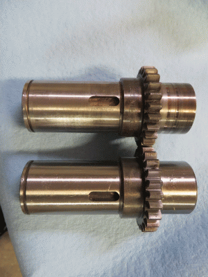
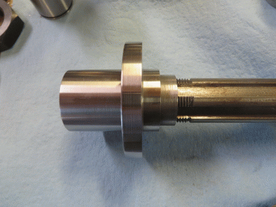
After searching several belt drive conversions of these types of mills the consensus is to use the existing splined shaft that couples the gears to the spindle. The gear is turned off the shaft and the end opposite the snap ring groove is threaded to accept a nut. One on my goals with this build is to not make any permanent modification that would prohibit the machine from being returned to it's original configuration as a manual mill. So to do this mode I needed another splined shaft. I like the people at Precision Mathews but they are still a growing company and not knowing how long it would take to get parts I dug around on the net and found the Grizzly G0755 to be the exact same mill. Ordering from Grizzly is easy so I ordered a splined shaft and had it in two days.

As expected the shafts are identical.
pm932_G0755_slpined_shaft_01.gif pm932_G0755_slpined_shaft_03.gif

The original shaft from my machine has score marks on it from casting grit in the gear oil rubbing in the seal so I will use that one for the modification and keep the new part as is.

The Grizzly part number is P0754057 http://www.grizzly.com/parts/P0755057

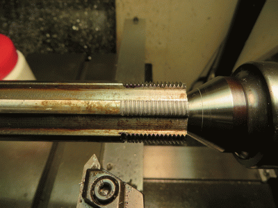
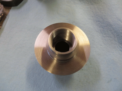
Before modifying the splined shaft I made some modifications to the spindle and turned a clamping nut for the power drawbar system. I have been using an impact wrench type system for a power drawbar but I have really come to dislike these systems. They are noisy, put a lot of stress on the bearings and tooling from the hammering and do not provide adequate torque for the TTS tooling system. On the CNCZone There is a thread about an electric drawbar using a stepper motor and a planetary gearbox. I'm really intrigued by this idea but unfortunately electronics are not my strong pint so I will be using a multi-stage air cylinder and bellville spring washer system for now. I plan on exploring the electric design in the future.

Spindle threaded to accept the clamping nut.
vsd_clamping_nut_01.gif

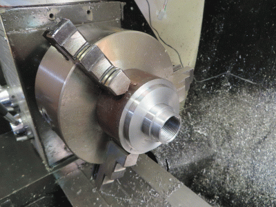
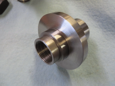
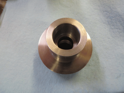
Clamping nut turned from 3-1/4" A36 steel.
vsd_clamping_nut_02.gif vsd_clamping_nut_03.gif vsd_clamping_nut_04.gif vsd_clamping_nut_05.gif vsd_clamping_nut_06.gif
 
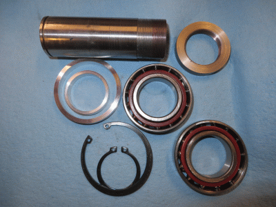
Made some good progress on the belt drive conversion this week. The spindle bearings have been changed to angular contact bearings. The bearings are a press fit so I had to heat / cool components to get the bearings to drop in. That all went well except I forgot to preload the bearings when I put the spindle in the quill body. After the parts had cooled and or warmed up the locknut on the spindle would not move the bearing. I ended up using a piece of pipe, with the ends turned true, over the splined end and made a shim the thickness of the up-down play in the bearings and used those to press the bearing into the proper position. Keeping my fingers crossed I got enough preload on the bearings .

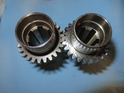
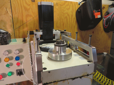
The pulleys are for poly-J belts. This has been used in a lot of other belt drive conversions so I went with it. The only downside is the vee-grooves are 40 deg. Carbide inserts for these are very expensive and seem to only come in 5 or 10 packs so the solution is to grind a cutter from HSS. I went with the typical 1:2, 2:1 pulley ratios. One thing to note is the splined sleeve has a pocket for a 6mm shaft key. I have a set of standard keyway broaches so I cut a 3/16" keyway in the pulley and made a 6mm to 3/16" adapter key out of 1/4" keyway stock.

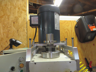
The spindle, head cap with spline drive, pulleys and motor are installed and I was able to manually run the motor for the first time tonight. Everything ran great up to full speed (about 7K rpm at 120hz). My biggest issue is the noise and some vibration from the splined sleeve/shaft area. I'm not sure if others have run into this same issue. It is a lot noisier than I expected but not nearly as noisy as the gear head. I will try and post a video of the noise problem later in the week.

spline drive pulley.gif spline drive parts.gif pulley swarf.gif belt drive 02.gif
 
....

My original plan was to maintain the quill travel but after getting more comfortable with the CNC machining I see no reason to keep that on so I now plan on fixing the quill in place. I'm curious how others have done this? I'm not sure I would trust the quill lock alone???
....
Jay
I use the quill lock by itself, it provides plenty of pressure to keep the quill from moving when in use, it also slips just barely to save me when I screw up. IE pressing the wrong button to cause the head to plunge into my part or into my tool height set gauge....... the gauge survived, the end mill did not. had the quill not slip under that pressure I would have lost both.
 
These are my VFD and Mach3 Spindle settings. Maybe it will be of some help to others.

On first setup I had trouble with the 0-10v PWM scaling between the VFD and Mach3. Any speed setting in Mach3 over 45% would send the motor full speed. Hours of searching and some help from PMDX support traced down the problem to VFD parameter PD072. This value needed to match PD005, the Max Operating Frequency. It was factory set to 400hz. I believe it took so long to find is that most of these Chinese drives are used with high speed spindles that operate at 400hz where as I am running a 60hz motor up to 105hz.

The PMDX-107 motor control has a great built-in calibration feature. Pressing the test button on the board for one second will start the motor at full speed for 30 seconds, a second press reduces the speed to 30%. This is great for isolating whether there is a problem with the VFD settings or in Mach3. To calibrate you set a trim pot at full CCW, press the test button and measure the spindle speed. The trim pot is used to adjust the spindle speed to match the expected full speed based on the motor/vfd/pulley settings.

My settings for PWM motor control with Mach3:

PMDX-126 BOB, PMDX-107 Motor Control, ESS Motion Controller.

MOTOR, 220v, 2hp, 3ph, 1725rpm, inverter duty, class F

VFD = Huanyang HY02D223B 3hp VFD Settings
pd001 = 1, run command = external terminals
pd002 = 1, operating frequency source = external terminals
pd003 = 60.00, main frequency
pdoo4 = 60.00, base frequency
pd005 = 105.00, max frequency (could be 120.00 with a better motor)
pd008 = 220, max voltage
pd014 = 5.0, acceleration time (user adjustable preference)
pd015 = 5.0, deceleration time (user adjustable preference)
pd070 = 0, analog input = 0-10v
pd072 = 105.00, Higher Analog Frequency
pd141 = 220, rated motor voltage
pd142 = 8.0, rated motor current (check your motor specs)
pd143 = 4, motor pole number (check your motor specs)
pd144 = 1725, rated motor revolution (check your motor specs)
pd176 = 60.00, inverter frequency standard


Ethernet Smooth Stepper Settings
SPINDLE
PWM, base hz 25


Mach3 Settings
RELAY CONTROL, disabled

MOTOR CONTROL
Use Spindle Motor Output
PWM Control
PWM Base Freq = 25
Minimum PWM 1% to 5%

SPINDLE MOTOR TUNING
Steps per = 1000
Velocity = 60
Acceleration = 5000

PULLEY SELECTION
Pulley 1, Min Speed = 0, Max Speed = 6000, Ratio = 2 (4" motor pulley, 2" spindle pulley)
Pulley 2, Min Speed = 0, Max Speed = 1500, Ratio = 0.5 (2" motor pulley, 4" spindle pulley)

Minimum speed needs to be zero or Mach3 will screw up the PWM scaling. If there needs to be a minimum motor rpm threshold it should be set in the VFD.
 
Back
Top