- Joined
- Jun 12, 2023
- Messages
- 42
Hello All
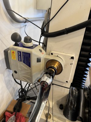
I been working on trying to adapt a power feed for the Z axis on my PM 932V mill. After much research and communications with PM tech department, all without any solutions, I have completed the project with an Align Z power feed kit. It was a fairly easy task that required minor modifications to the kit.
My apologizes for not having detail pictures, I didn't think to post it until after I was completed but the few I have should show you what I did to accomplish this:
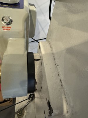
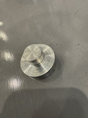
First I made a centering jig to center the existing round plate that centered the existing shaft. This is mounted to the side of the mill where the existing Z handle is located.
I then mounted the new mounting plate and the existing round plate from the machine to the jig and drill and tapped holes matching the 3 hole locations in the new mounting ring. You will need to index the two rings to the desired position of the power feed you desire by aligning the 2 mounting hole for the power feed body in that position. I flipped the new mounting ring over and counter sunk the 3 existing hole locations from the raised center side of the ring. The raised area fits the power feed diameter and centers the ring onto the power feed. You will need to supply counter sink screws to match your application. The counter sink holes may extend into the raised area of the ring, it did not effect the fit.
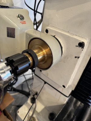
The extension shaft provided with the kit did not fit the existing shaft on the machine so I had to take about 10 thou off the threaded area and extend the bore into the extension shaft to the necessary depth of the existing shaft. I'm sure they are all different length so you will need to measure your specific shaft and its diameter prior to boring it.
Once it is bored to proper diameter, mount the existing ring back onto the machine and slide the extension shaft over the existing shaft until the extension shaft bottoms on the existing ring plate. Mount the new ring onto the old ring using the hardware and holes you drilled an tapped. Dry fit the power feed onto the shaft and ensure the bearing area of the shaft is flush with the power feed if it is not:
You may also need to turn the bearing area of the extension shaft back about 20-30 thou so it will not protrude beyond the bearing housing on the power feed, or you can machine the necessary amount from the end of the shaft to move it back enough so it will not protrude. If you cannot get the teeth to engage the shaft is what is not allowing the brass gear to fully seat. I did not realize this until I already drilled the hole for the pin to lock the shafts so I removed the material from the bearing area.
Once everything fits properly, remove the new ring, you will need to provide an appropriate sized dowel pin and drill the extension shaft and existing shaft to install the pin and lock the two shafts together. This pin will need to be within the new ring area so it will need to be flush with the extension shaft diameter so it can spin inside the new ring without interference.
The rest of the installation is outlined in the instructions with the power feed and there are no other modifications necessary.
I also purchased a handle from Amazon to match the configuration of the extension shaft 9 tooth clutch. $30.00
The torque necessary to rotate the Z axis was measured at 25lbft. The Align feed was rated well beyond that, there are other units less expensive that provide specs above this as well. I chose Align because it had the highest torque available and I wanted trouble free operation. You can also make a dummy dial to cover the brass gear but I did not think that was necessary.
Hope this helps anyone tiered of cranking the Z up and down on this machine.


