- Joined
- Jan 2, 2014
- Messages
- 9,598
Okay this saw has been waiting far too long!
I will show a little bit of the motor controller in another post......I got lucky that this one just needed an analog voltage to vary the motor speed.
I knew I wanted to add a speed reduction between the motor and the saw input shaft. I went looking around for options and thought about pulleys and counter shafts. In the end, I decided to use a worm-gear speed reducer that I had picked up many years ago for another project that never happened. (I was thinking about building a dividing head loosely based on the Gingery design; but that project took so long to start that I ended up buying one in the mean-time).


I forgot to put a scale in the picture (again!), but the body that thing is about 5" wide, 6" tall and 3" thick.
The input shaft is 5/8" and the output shaft is 1". Both shafts have key ways.
That worm gear has likely been sitting in a box on the shelf for 15 years....time to put it to use.
Next I needed a coupler between the motor output shaft and the worm-gear input shaft.
The motor output shaft is threaded M14-2.0 on the end, but with a long 16mm shoulder.
I thought a Lovejoy coupling was what I wanted, they will put up with some misalignment.
However, I knew the local hardware store wouldn't have anything....and I also could not walk into the nearest most likely place to carry one (a fastener supply place in Ottawa) due to the pandemic lock-downs.....so I started to think about building one......
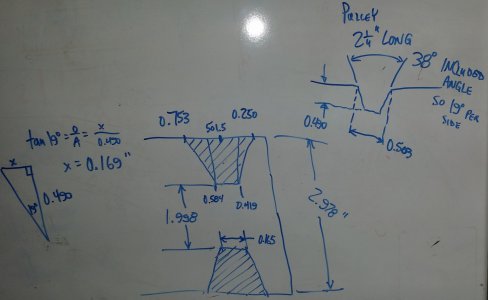
Once I got the idea of using a hockey puck, I just had to make one.
I cut two pieces of 1/4" steel plate, and turned some bushings to weld on.....and got this:
the motor (input) end:

the output end:

Those photos above were taken before the pins/tines were welded in......

A hockey-puck based homemade Lovejoy-type coupler!
Here's a test fit in the saw:

That is the band-saw input pulley at the top of the photo.
I welded a base onto those odd-shaped motor mounts and bolted both to a rusty piece of channel.
Here's a motor test:
View attachment motor_and_worm.mp4
Sorry about all the loose bits on the bench rattling around.
Getting closer........
-brino
I will show a little bit of the motor controller in another post......I got lucky that this one just needed an analog voltage to vary the motor speed.
I knew I wanted to add a speed reduction between the motor and the saw input shaft. I went looking around for options and thought about pulleys and counter shafts. In the end, I decided to use a worm-gear speed reducer that I had picked up many years ago for another project that never happened. (I was thinking about building a dividing head loosely based on the Gingery design; but that project took so long to start that I ended up buying one in the mean-time).


I forgot to put a scale in the picture (again!), but the body that thing is about 5" wide, 6" tall and 3" thick.
The input shaft is 5/8" and the output shaft is 1". Both shafts have key ways.
That worm gear has likely been sitting in a box on the shelf for 15 years....time to put it to use.
Next I needed a coupler between the motor output shaft and the worm-gear input shaft.
The motor output shaft is threaded M14-2.0 on the end, but with a long 16mm shoulder.
I thought a Lovejoy coupling was what I wanted, they will put up with some misalignment.
However, I knew the local hardware store wouldn't have anything....and I also could not walk into the nearest most likely place to carry one (a fastener supply place in Ottawa) due to the pandemic lock-downs.....so I started to think about building one......
Once I got the idea of using a hockey puck, I just had to make one.
I cut two pieces of 1/4" steel plate, and turned some bushings to weld on.....and got this:
the motor (input) end:

the output end:

Those photos above were taken before the pins/tines were welded in......

A hockey-puck based homemade Lovejoy-type coupler!
Here's a test fit in the saw:

That is the band-saw input pulley at the top of the photo.
I welded a base onto those odd-shaped motor mounts and bolted both to a rusty piece of channel.
Here's a motor test:
View attachment motor_and_worm.mp4
Sorry about all the loose bits on the bench rattling around.
Getting closer........
-brino
Last edited:


