Need help wiring drum switch.

Hey Clif, picture is much better though, a little confusing. Like Mark said, 220 volt may end up being easier.
I need another picture to make some sense of the label plate.
There should be a cover plate on the motor where one would connect the incoming power wires.
Take the cover off and take a close-up picture of the wiring connections.
Per the label plate, there should be 4 connection terminals and they should be labeled 1 through 4.
This will show us how the motor is currently connected either for 110 or 220.
It might help clear up my question on the label plate as well.

From your drawing of your drum switch connections, it looks very similar to the one on my mill. I wired it for 220 and I'm guessing yours will end up the same or similar
 
clif do you have a multimeter of some kind?

Yes, and very basic knowledge on using it. Shorts in automotive wiring, finding resistance, and voltage across wires and components.

Have you done any electrical work?

Both residential wiring, including my entire shop, to include building from scratch a three phase converter.

Some stereo and appliance repair. Made my first treadmill motor controller from a MC-60 board, for my wood band saw.

This will show us how the motor is currently connected either for 110 or 220.

I can state the machine currently is wired for 110, both by the plug it has, and from the gentleman I got it from had no 220 circuits near the lathe when I picked it up, only 20 amp 110 plugs.

All the machine had was a single wire on off switch, on the top of the spindle cover in the recess, looks OEM due to the recess cast in for the switch.

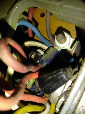
Here are the pictures from inside the motor wiring connections, very crowded in there.
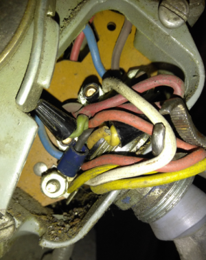
IMG_20171011_124608.png IMG_20171011_124455.jpg

I see four screws with nuts on the board
 
Last edited:
Hi clif, I have no doubt you have enough skill to get this working; I'll have to run you through a few tests on the motor wiring before we know what is what.
I think we would be best served by abandoning the factory wire swaps and do the "swinging start leg" arrangement, wiring for 230 volt. It's much simpler.
First step: Disconnect the wiring completely, get it down to just the motor as it came from the factory.
Second step: ID the two run windings with your ohmmeter.
Third step: Locate the other end of the start leg and bring it out. Verify start leg behavior with meter.
Fourth step: Rewire according to the diagram I will provide.
Fifth step: Fire it up. Smile. Make chips. Send me suitcases of money (optional)
Mark S.
 
Like Clif said, remove the incoming wires from the motor. I'd like to see a close-up picture of the terminals once the wires are disconnected.
Take a close-up of the terminals with the motor wires still connected to the terminals if you can.
This is where you need to have a little care as the wire colors don't always match the label plate colors.
 
Here is a diagram of (I believe) the inside of your motor-
 

Attachments

  • USmotor1a.pdf
    561.1 KB · Views: 15
Hey Mark,
I took the label plate data and found this wiring diagram on Graingers.
 

Attachments

  • Dayton.pdf
    94 KB · Views: 23
Hi Pigg, I see two places on the Grainger diagram that doesn't match up to his motor
1) the thermal switch wire colors
2) the black start leg wire isn't brought out on his motor, and it may not even be black
The one I posted I think is a little closer to his
On the diagram I drew the thermal switch is still in the blue line, I just didn't show it- It won't affect
anything having it there
M
 
Last edited:
clif: I think you can skip the second step and go to step 3. Need to open the terminal board (you may have to open the motor case) and look for the wire ?black?behind the terminal board.
It will be connected to one of the line side terminals probably #4 and may not be black.
Post some pics too when you get to that point, we need to do a check with your meter
Mark S.
 
Back
Top