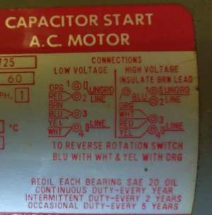
Need help wiring drum switch.

clif

H-M Supporter - Gold Member
H-M Supporter Gold Member
Joined
Sep 8, 2014
Messages
38
I have a Atlas 3986 lathe which I want to wire to run in reverse to allow metric threading.

I have a Dayton 1/2 hp 100/220v reversible motor and a Dayton drum switch. I have read several threads here and elsewhere about this but do not see any the have the wiring connections to reverse I have on my motor.


Drum switch is a Dayton 2X441/RS-1


motor name plate;
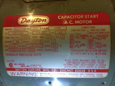

IMG_20170924_220444.jpg

Anybody have any ideas how to do this?

Most of the threads have one set of wires being reversed, the name plate has two.

to reverse rotation switch blu with wht & yel with org

How do you do that with a this drum switch?

The drum switch internally is operates like this;
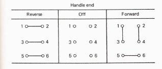
drum switch.jpg

Any ideas how this would be done?
 
It can't be done with that drum switch. At least not without knowing where the six wire leads go and what the internal connections are between the four screw terminals and the two spade terminals. What is really puzzling is the brown wire which must be insulated for the 240V connection. And the fact that two pair of wires must be swapped to reverse. On a dual-voltage single phase motor, there are normally three windings, two RUN and one START. The usual thing for reversing is to swap the two START circuit wires. But you could swap the four RUN circuit wires if you wanted to complicate matters. But I can't think of any good reason to do that. I think that your best bet is to decide whether you want to wire it for 120 or 240 V and take the motor and switch to a motor shop and let them figure it out.

I don't mean to be insulting when I say that probably if you knew enough about electric motor circuits to be able to correctly measure and draw out the actual motor and junction box wiring diagram, you wouldn't need to ask for help.
 
the drum switch may be able to be wired in for directional control, but you may need an auxiliary toggle switch for power disconnect.
i'll take a look at the diagram and see if i can offer a solution when i get home from work
 
This is possible with the switch you have but the difficulty is identifying the internal motor connections- you usually need an ohmmeter or some type
of continuity checker. I have several satisfied customers on this forum so far, Ulma and I'll help you out. Stay tuned
Mark S.
ps that brown lead is part of a thermal protector circuit; many motors don't use it for the 230v case. Are you planning on using this motor on 115 or 230v?
 
Yes, it can be done and not that difficult (I think).
What voltage supply do you intend to use ??? 110 or 220 ???
Post it here and I'll take a look. Post a closer in, larger picture of the wiring details for your motor as well. My eyes aren't as sharp as they used to be. LOL
 
it boils down to having to swap 4 wires - Blue and White, Yellow and Orange in 220v mode for directional control
you may need a relay to use the drum switch
i'm trying to run through ways of doing it with what you got :)
 
So guys here's my take: blue and white must be one run winding, yellow and orange the other one. The start leg must be red and (probably) the bottom Line terminal (permanently connected behind the terminal board)
The nameplate says to swap both run windings to reverse; Difficult to do with the drum switch he's got. If we could find and bring out the other end of the start leg that would be the simple way; for 230v you would switch that one wire from one side of the Line power to the other to reverse, leaving the red at the midpoint of the run windings.
Pigg you probably see where I'm going with this.. I'll do a sketch, give me a little time.
Might be simpler to do that rather than trying to do the 115v case considering all the wires that would have to be brought out.
What do you guys think?
Mark S.
ps this is the first time I've seen a nameplate tell you to swap the run windings instead of the start leg.
 
Last edited:
Back
Top