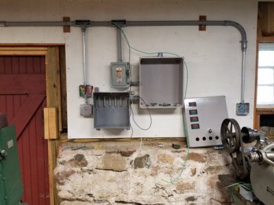
Keith, thank you for taking the time to share the details. I appreciate the explanation. As a teen, I got pretty good at following the plans, but missed learning how the stuff actually worked. Now I'm trying to improve upon that.
Hi Dave H. (the other one), I'm Jason No. 3 (or was it No. 4). Thank you too. It's always nice to have more than one way to look at a solution.
Two items I still wanted to clarify, there are; 1) no issues mixing start and run capacitors in the start circuit, and 2) no issues allowing a RPC to run without a load for an extended period of time. That is my understanding at this point.
I have noticed a couple plans which include two start circuits. Paul actually designed for two potential relays but only used one. At first I thought maybe this would allow the system to be calibrated to different pieces of equipment but that doesn't make sense unless you have more than one idler motor which these do not. What is the reason for the second circuit?

