Mule look alike

Hi Marcel, will have to fabricate a new axle, the existing cast iron one will be too narrow. Think it will be easier to start from scratch, I'd have to find cast iron material to extend it and the geometry wouldn't be right in the end.
From what I've researched the camber is simply set to place the pivot point when your steering in the middle of the tire face. Does that make sense?

Greg
 
The axles in that cub rear end are spliced just like car axles. Remove rear cover, pull out clips and remove axle shafts. Google will give you all the answers for switching the rotation but as I remember there is a plate with angled holes that messes you up. That Sundstrand hydro unit was designed for much bigger machines then that tractor so pretty much bullet proof.
 
Hi Greg
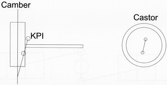
The front end geometer has to be something like this .
camber and king pin inclination have to meet just below the point of contact to give the wheels a slight bias to turn outwards this is corrected by setting the track arms to toe in 1/8 " keeping the wheels in tension stopping them flapping about ,

The king pins must have some angle, top backwards (castor ) to make the steering self centre and stop it diving left or right on bumpy ground.

img007.jpg


Hope this helps.
Brian

img007.jpg
 
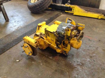
The axles in that cub rear end are spliced just like car axles. Remove rear cover, pull out clips and remove axle shafts. Google will give you all the answers for switching the rotation but as I remember there is a plate with angled holes that messes you up. That Sundstrand hydro unit was designed for much bigger machines then that tractor so pretty much bullet proof.

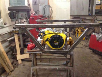
The plan is to mount the engine behind the axle, this solves my rotation problem and puts the engine more in the open for maintenance.
Your right that drive is built heavy, just put it on the scales and it topped out at 175 pounds.
IMG_1495.jpg

Greg

IMG_1495.jpg
 
Hi Greg
The front end geometer has to be something like this .
camber and king pin inclination have to meet just below the point of contact to give the wheels a slight bias to turn outwards this is corrected by setting the track arms to toe in 1/8 " keeping the wheels in tension stopping them flapping about ,

The king pins must have some angle, top backwards (castor ) to make the steering self centre and stop it diving left or right on bumpy ground.

View attachment 87797


Hope this helps.
Brian

Thanks Brian,
The way you have it shown with the camber angle meeting the centreline of the tire below the face, when the tire is steered it would have to roll slightly, around the point where the camber angle meets the face. Is that what is desired? If the camber line met the tire centre line at the tire face then it would simply spin when the tire is steered. Im thinking more of moving the steering while the vehicle is stopped. Maybe with your design its easier to steer with the tire rolling slightly than my geometry where the face has to slide. OR does the camber angle interact and move that rotation point some where else. I sometimes have a hard time thinking of motions in 3D.

Greg
 
Todays progress.
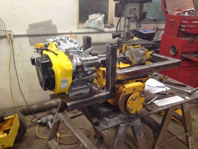
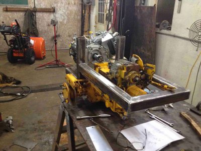
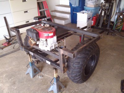
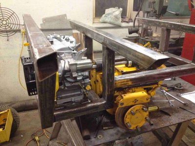
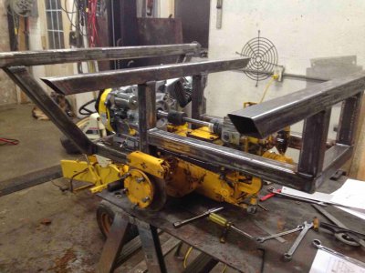
Bolted the rear part of the frame to the transaxle, had to make a couple of recesses to clear bolts that looked like they'd miss in the original design. After a couple of attempts I got the motor mounting plate to fit, (made a new drawing on the shop computer but read the dimensions on the print wrong, the plasma cuts out exactly what you tell it).
The good news is the shafts line up. Will have to put a bit of a twist in the exhaust to clear the frame but that shouldn't be an issue,

IMG_1497.jpg

IMG_1498.jpg

Now I need to find some suitable sized tires and rims to finish designing the front.

Greg

IMG_1497.jpg IMG_1498.jpg
 
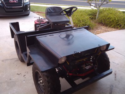
Fun project! Here's a couple of my mini-jeep for inspiration.

uploadfromtaptalk1416124908603.jpg uploadfromtaptalk1416124929617.jpg uploadfromtaptalk1416124946829.jpg uploadfromtaptalk1416124967805.jpg
 
Hi Greg
If you have the angles meeting at the surface the wheels are likely to shimmy like a poor supermarket trolley. the idea is to make the wheels want to turn outwards putting the joints on the track rod under tension and taking up any slackness
in the joints (even new ones) this amount of offset will not affect steering loads.
By the way the angle of the steering arms is critical to get the wheels to follow the correct path in turns (Ackerman steering ) The quick and dirty way to determine this is to take a line from the centre of the king pin to the centre of the rear axle. the arms must follow this line. the arms can be curved to clear things if necessary but the joint at end must be on this line.

Looking forward to seeing this in action.

Brian

Edit?? with the very short wheel base you may have to compromise and take a point behind the axle or it may limit the turning circle?? just look out that the joints on the inner wheel do not pull straight and lock out on tight turns . you will need lock stops on the axle also.
 
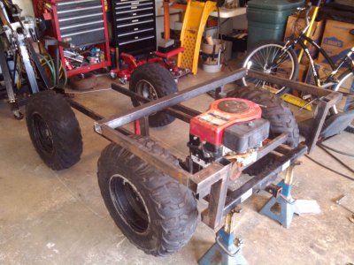
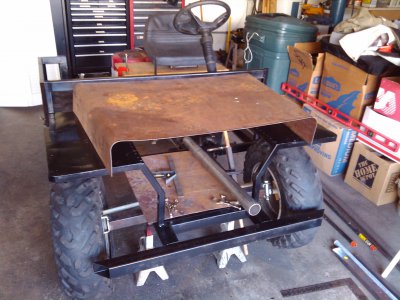
More progress on the frame. Im using (recycling) old tube I got a while back, think it was some form of racks or shelling. Its rusty but still has a certain amount of paint, took me an hour this morn to clean up 3, 6 foot lengths. If I valued my time it would probably be more cost effective to have bought new material.

IMG_1500.jpg

IMG_1502.jpg

IMG_1503.jpg

Greg

IMG_1500.jpg IMG_1502.jpg IMG_1503.jpg
 
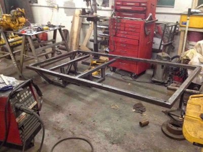
More tube cleaning and we have the size established. Had planned on 8 feet long but looks like it will be 7 foot 7 inch by 46 wide. Drilled the side rails and welded in 3/4 pipe for stake pockets, easier than cutting square holes that line up top to bottom.
IMG_1504.jpg

Greg

IMG_1504.jpg
 
Back
Top