Mini Mill X Power Feed

Hi Ferlum, thank you.

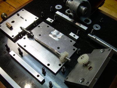
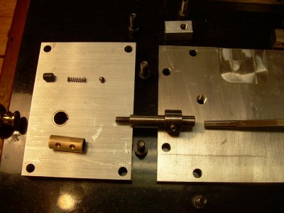
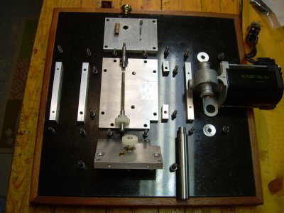
I turned a portion of the square bar (4 mm key stock) round, then drilled the round 1/4 inch shaft to match. Used loctite and the pin that locks the gear also locks the two shafts. On the other end, the shafts are secured with a #6 set screw.

Wagner
 
Last edited by a moderator:
Thank you sir! The pictures are very helpful. I'm working on a similar version right now.
 
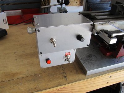
OK here's my attempt :)

It's not as nicely executed as Wagner's but it works :)

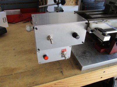
I put the speed controller and power jack in the smaller extruded aluminum project box and mounted it under the main enclosure. The speed controller is a $6 ebay item. I got the same gears that Wagner used from McMaster. The motor, toggle switches and power jack are from All Electronics. The 12 volt power supply (6 amp) came from ebay (it could be a little more powerful -- if I attempt to run the unit with the speed control past 60-70% it won't start. Which in a way is an unintentional safety feature that prevents a sudden fast start).

It works great and the motor seems like it's very durable has plenty of torque.

I just picked up a Taiwan-made Enco 9X20 lathe so the drive shaft components were my first "real" turning project. I've been a hobby machinist for about a year and this was my most complex project to date -- I had to make a few parts twice but it was a lot of fun and a great learning experience.

Thanks again to Wagner for the original design :)

14l5zlh.jpg

14l5zlh.jpg
 
Hi Ferlum, It looks great.

I'm very happy that you implemented it successfully.

I too used a 6 A power supply, and the unit could use a little more power.

With the pot up to about a third, the motor did not start, and on the upper side on the last third or so, the motor pulled so much current that the power supply just shut down.

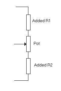
To solve this I've installed a couple of resistors on the potentiometer:

Pot.JPG
With the resistors installed, the full range of the pot is used. I've played with resistors values so the motor will run very slowly with the pot at zero and don't disarm the power supply at full pot. I don't remember the exact values, but I think they are close to 33 K Ohms.

Wagner

And I like the turned knob...
 
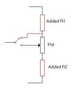
And this is the "Turtle/Rabbit" switch:
Pot2.JPG
Edit: This is the corrected diagram.
 
Last edited by a moderator:
Thanks for those details Wagner. I was wondering about your turtle/rabbit circuit. Electronics is not my strong suit.

So far I have not experienced the over-current shutdown, maybe my speed controller is a little different. But I'm saving your schematics for future reference.
 
Is this setup still working well for you?
With the change in the weather and more free time I may have to do one myself.
 
Is this setup still working well for you?
With the change in the weather and more free time I may have to do one myself.

I only have an hour or two on mine but it works great. I like it so much I bought a second motor for a backup -- I figure if anything else breaks I can make another part, but if the motor dies and I can't find an exact replacement I'm kind of screwed.

It was fun to make and it's extremely nice to have the benefits of power feed.

My version is simpler than Wagner's (no rabbit/turtle switch) . The speed range is perfect -- it goes from barely moving to way faster than I'd use for actual cutting (which is good for moving things around when setting up for a cut, etc.) I bought the speed controller and motor first and wired them up to get a warm and fuzzy that the speed was usable before I started fabricating.

Here's the speed controller I used:

http://www.ebay.com/itm/6-90V-15A-D...PWM-Speed-Regulator-Switch-16KHz/261417338800

The 12v 6a power supply:

http://www.ebay.com/itm/11171405623...49&var=410714804872&ssPageName=STRK:MEBIDX:IT

The project box for the electronics that's mounted under the main enclosure:

http://www.ebay.com/itm/321797600037?_trksid=p2057872.m2749.l2649&ssPageName=STRK:MEBIDX:IT

Mine does not have the ball bearing/spring mechanism that holds the shaft in the engaged/disengaged positions that Wagner's has, but I'll probably end up adding something to accomplish that. It hasn't disengaged itself but it does tend to move a bit. Might try a stiff spring that pushes the drive shaft to the right to hold the shaft/gears in the engaged position. That would require one hand on the knob during manual handwheel use (or a little part that fits between the knob and the enclosure to temporarily lock it in the disengaged position), but I think I can live with that.
 
Back
Top