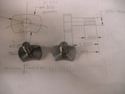
One of your posts made me think that you were trying to figure out how to mill one end of the boring table to mount a compound. If so, why would you want to do that?
[Hi, Robert. You can move this thread if it seems warranted, but I'll also create a separate thread in the Sheldon/Logan/Rockwell forum with pictures from the build as I make more progress.]
Rather than having a separate cross slide for line boring or whatever, I wanted to replace the factory cross slide. As one example, it would be convenient to have a cut-off tool in a rear mounted toolpost while still leaving a turning tool in the toolpost on the compound slide. It's also nice to have a "deck" for something as mundane as attaching an indicator mag base. The rear mounted screw cover that attaches to the factory cross-slide on my old Logan is (annoyingly) both curved and made of something non-ferrous (maybe zinc?).
I think this is the most common way to use that casting from Metal Lathe Accessories. The drawings that Andy sent me with the casting show expressly how to attach a South Bend compound (and Paula in the Practical Machinist Forum did the same). I'm just trying to modify the design to work with a Logan rather than a South Bend lathe.
I've been away from the shop for several days, but after mulling it over in my head I'm pretty sure this will work fine. My plan is to leave the top completely flat, except for a pressed-in 1/2" locating pin for the compound, and the milled circular and straight slots. The original slide has a raised circular area for the compound to ride upon, as shown in my first post, but I can't imagine that being a problem. I haven't measured yet, but I think I can move the pin (and compound) back far enough to allow for the other work-holding attachment points (tapped holes) in Andy's design, but this is about the only thing I'm unsure of at this point.
I also lost about 1/8" of travel on my cross slide when I made larger replacement dials. Rather than making a longer screw or somehow moving the dial back, I'll likely move the compound further back on the casting to reclaim the lost travel. This will mean the round part of the compound won't be visually centered with the round part of the casting, but the compound base fits within the straight sides, so I'll probably just mill off the "ears" (the round part of the casting).
My hope is that most of the time I'll just leave my compound attached, but still have enough room in the back for rigid attachment of tooling or workpieces. When necessary, I can remove the compound to give me more room. If the locating pin ever gets in the way, I can make a flat sub-base out of cold-rolled with a hole for the pin to give me a continuous flat surface
All of this will be clearer with drawings and photos which I will include in the new thread on the other forum. Here's hoping it doesn't end in tears.
73
--
Rex

