Manual Operation After Cnc Conversion

JimH

I have to agree with what you said above. My machine is not a normal hobby machine. But if my DC servos ever fail, I have a set of 1280 oz/in NEMA 34 steppers on the shelf that are going on the mill. The DC servos are ~425 oz/in, but the torque curve is nearly flat on them.
 
Jim and Jim H. - Thank you so much! Exactly what I wanted to know. Nothing like truly informed information. Thank you for taking the time to share your knowledge.

I really try to do my research before asking questions. Getting started gets pretty complicated and overwhelming quite quickly. So many options and options within options. My background is computer programming and I know a little bit about electronics, but even with research I constantly come up with electrical and engineering questions that I don't know enough about to answer myself. Very frustrating!

Jim H., That inertia and torque info is amazing and eye opening. Very cool. I'll remove the handles! Thanks for the motor info too. Most helpful.

Again, thanks. You wouldn't believe how helpful it is to have such informed assistance when getting started. It makes a world of difference!

Mark
 
The link works for me, but here is the URL again.
www.leadshine.com/productdetail.aspx?type=products&category=stepper-products&producttype=2-phase-stepper-motors&series=57HS&model=57HS22

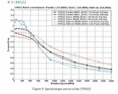
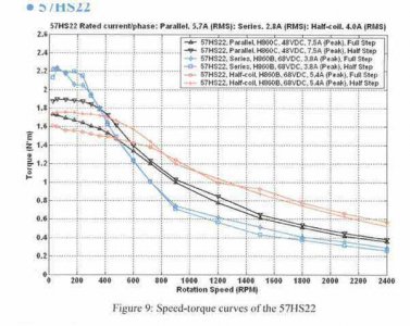
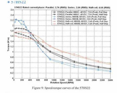
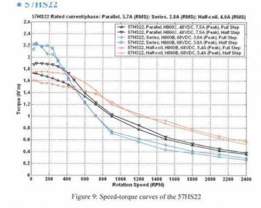
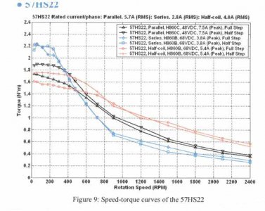
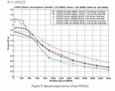
And here's the graph.
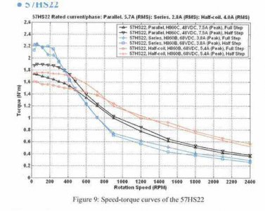
Graph2_1.jpg
The curve is for a Leadshine 57HS22, with a rated holding torque of 311 Oz-in. (2.2 Nm) - most importantly, the body of the motor is 81mm long.
For any frame size stepper, in general, the longer the motor the greater the holding torque, and the higher the inductance - so the torque drops off sooner as speed increases

In my case, 1000RPM is close to 200ipm if the motor is direct coupled.
But the curve shows the maximum torque that the motor can put out. And generally with steppers, you want to design/calculate at 40% of that value. This motor produces about .66 Nm max at 1000 rpm (for the blue line - series connection) so about 27 watts of useful power. And the blue line is darn near hyperbolic from 250 rpm out, so basically "constant power".

Jim D. - I've never used a brushed DC servo, but with AC servos the rated torque is what they can pull to rated rpm with 100% duty cycle, then are close to constant hp to maximum speed. Below rated rpm, they have between 2 and 3 times rated torque available for accelerations and other transients - and then being closed loop, it really doesn't matter if they lag a little bit.
Graph2.jpg

Graph2_1.jpg

Graph2_1.jpg

Graph2_1.jpg

Graph2_1.jpg

Graph2_1.jpg
 
Graph3%202.jpg
Jim - this is is the curve for Leadshine's 1200 oz-in Nema38.
Are your spare motors 8 lead? If so, the parallel graph could apply.

Graph3%202.jpg

Graph3%202.jpg

Graph3%202.jpg

Graph3%202.jpg

Graph3%202.jpg
 
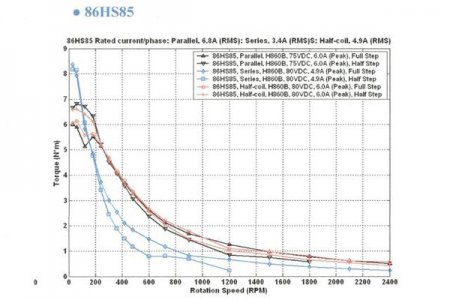
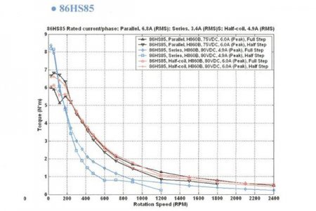
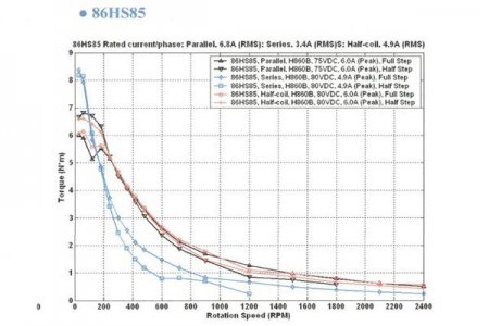
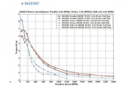
Here is the curve on the NEMA 34 motors I have. 4 wire motors

upload_2016-2-22_18-39-22.png
 
Those graphs are interesting. I hadn't thought about what rpm the motors are running at. That is helpful in understanding why Jim H. says use 40% for calculations.

What sort of RPM do motors run at for low, medium and fast movement? Do they ever get maxed out or do the drives keep them more or less mid range RPM? Torque is pretty much in the dumper at high RPM. At the end of a fast move, that is right when high torque would be needed to overcome the inertia of those apparently freakishly heavy handle flywheels if they were not removed! :)

Let me guess... Jim H. said, "if I gear them for 100 ipm at 1000 rpm", so it would depend on the screw, or if you had geared motors, and what you set ipm at? Forgive me, I'm just getting started.:rolleyes:
 
Last edited:
Assuming a normal 0.200 pitch lead screw = one inch per 5 revolutions. So 5 revolutions per second * 60 seconds = 300 rpm = 60 inches per minute. Normal cutting speeds would put you into the 20 to 100 RPM range, so almost full torque available for cutting. A normal rapid on your machine might be 100 IPM, so about 500 RPM max
 
Wow! That was an extremely informative bunch of posts. Thanks guys!
 
The critical thing to remember is that steppers are open-loop control. The command goes out, and the controller assumes that the move is made... End of story.
The controller must be configured to stay within the limits of the electro/mechanical system. It must command moves that are well below the threshold where it loses steps.
To determine those limits, all you can do is test the actual installation, and determine what the system can do.

Closed loop control is an entirely different animal...

With steppers, the rapids are where the limits will be touched. The sophistication of the motion control also enters into it.
 
Back
Top