Hello all,
This is all very new to me and experts will certainly frown ... but maybe this will help other folks new to machining. TLDR: below is a VERY quick and dirty way I was able to get a better shape for a hand-ground gear tooth cutter.
I want to make gears for the Sherline threading attachment outside of the range that Sherline sells. I would be willing to buy a commercial cutter, but no luck (I got one, 24 pitch, correct "number", but it did not seem to fit and was dull...). By the way, could someone on this forum advise if there is a matching one out there??? Sherline had no info for me on this. OK, so the only option, and Sherline's suggestion, and generally a good thing to have experience in, is to grind one myself.
I ground one as an experiment and it kind of worked, but I could not grind the cutter to the right shape. I believe that was to a large extent because I could not repeatably hold the cutter and the template gear next to each other in the same position to see where to grind off the next tiny bit; every time it would be angled a little differently and I was chasing my tail.
I wanted to make a holder where a gear and the cutter being ground could be held next to each other in a repeatable way. I had / have an overall design in my head, but I realized after agonizing over this for a while that it's outside of the scope of what I can do at this time. But I was able to make a MUCH less ambiguous version with three business cards, six staples, and two spring clamps. OK, and something flat to clamp it down to. It worked VERY well in relation to the effort invested.
Please find the pictures below. I scribed some lines along the center line of the bottom business card to help with alignment; they are probably invisible in the pictures. I cut one card into four pieces, stapled two of them (stacked), put the cutter blank next to them, stapled two more pieces on the other side. This worked out very well indeed; the cutter "clicks" into this "channel", can slide back and forth, but does not move in any other way (to the extent relevant for this low-precision operation). I cut up another card into four pieces, stapled them on top of each other, and put the template gear on top; this is needed because it is thinner than the cutter. The whole thing was kind of flimsy so I used the spring clamps and a piece of plastic as a backing; one of the clamps also holds the template gear; this also worked surprisingly well, the gear would not move, I had to decrease the pressure on the clamp to tweak its position.
It would be nice to have a hole in the area where the cutter and the gear meet so that you can shine the light from the other side. I did not do it because I wanted to see those scribed lines on the card for aligning the gear, but I think I will find a way next time.
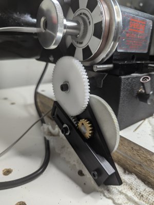
I started with a standard bench grinder, then a diamond wheel on a tiny benchtop polisher to get closer. Resulting shape is not perfect but a lot better than last time. Most importantly, this time I felt that the thing I am struggling with is the grinding, not the holding-of-gear-and-cutter-next-to-each-other, so it feels like a step forward.
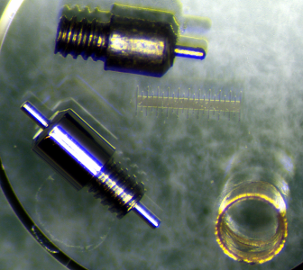
Extra observation 1: Sherline's gears have big "burrs" at the end of their teeth -- I am not even sure if that's the right name for it, they are like turned-over slices of aluminum. I guess they were made by a broaching-like process and that's a side effect? Any way, that probably does not affect the functionality because this outer edge of the tooth does not come into play, but it makes tooth shape irregular, makes gears harder to measure, looks ugly, and more to the point makes it a lot harder to use them as a template for a gear cutter. So I removed this burr on the lathe and lightly sanded the teeth. TBH I have not yet tested how that works, but it sure helped with the grinding operation. See one of the pictures (sorry about the poor quality but you will know exactly what I mean if you look at these gears under magnification) showing "as is" and "cleaned up" gears next to each other.
Extra observation 2: Sherline's pictures suggest that one would use the entire standard-length cutter blank in their gear cutting attachment. I had better results (as in, not stalling the lathe all the time) after cutting the blank in half (with a Dremel) so that the cutting part just slightly sticks out of the holder. (I suppose it might also help to use a heavier holder; maybe adapt their "chuck blank"? What do you think?)
Very best,
-Pavel