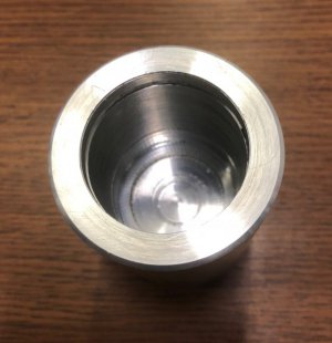
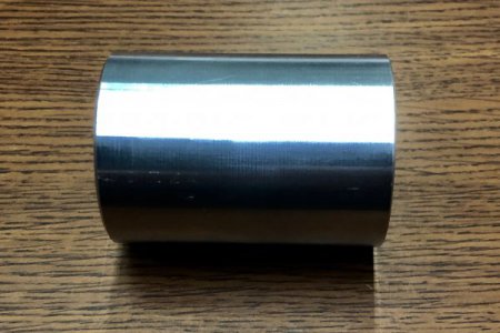
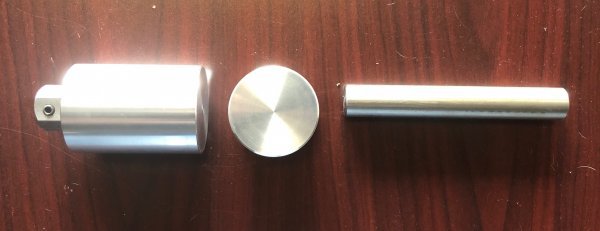
A couple years ago, I made a very quick and dirty rotary broach for a project i was working on in my normal job

 www.hobby-machinist.com
it worked for the purpose it was intended, but i wanted to make an improved version.
the new version , i envisioned was precise, robust, and economical.
(i priced out a manufactured rotary broach similar to the size i'm constructing, it was over $500 USD)
last week, i took up the gauntlet, to make my vision a reality (and for a lot less money )
)
as an added challenge, i'm going to do this project ,with only the stuff i have lying around the shop
ACT 1: The Capsule
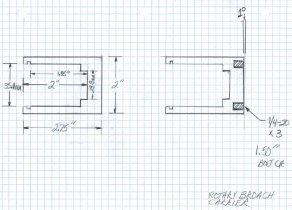
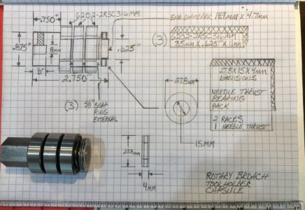
after hunting down the materials, i decided to draw a plan for the capsule
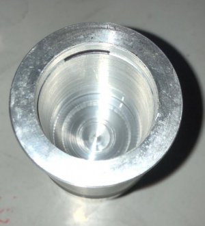
the capsule is a sub-assembly of the rotary broach.
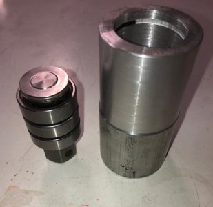
the capsule contains the toolholder shaft, roller bearing and thrust bearing assemblies, and their spacers and retainers.
it is designed to be taken apart for easy bearing changes, as necessary.
enjoy!
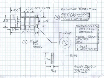
i had [3] 6202-2RSC316MM ball bearings, and a needle thrust bearing in the shop, so the capsule was built around those specifications.
[side note: 6202-2rsc316mm is a special bearing, the outside and thickness are metric dimensions, the ID is imperial]{also, the bearings are 316 stainless}
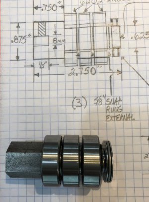
the broach holder was constructed from .875" hexagonal unknownium steel stock to a finished length of 2.750"
3 grooves were added to the broach holder for bearing retention by 5/8" external snap rings
i constructed 3 spacers from aluminum to provide extra clearance between the ball bearings
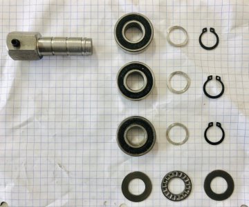
the main part of the broach holder shaft was turned to .625"
the distal end of the broach holder was turned to metric dimensions 14.9mm for a distance of 4.7mm, to accept the needle thrust bearing (27.8x15x4)
the proximal end was drilled to 7.5mm and then reamed to 8mm
then the broach retainer screw was added, i drilled and tapped for a 1/4-20 x 1/2" set screw
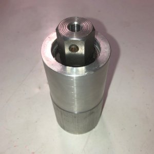
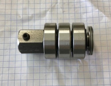
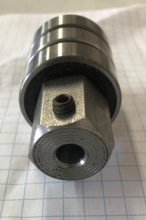
here is the capsule fully assembled
Stay Tuned for Act 2...... (if you dare)

Shop Made Rotary Broach, Down And Dirty!
Shop Made Rotary Broach i have a job that requires a square hole to be pierced through a piece of machined steel. the material is too thin to be push broached for fear of fracture. i don't have pull broaches or the puller for that matter, so i'm doing the next easiest method i have seen. i...
 www.hobby-machinist.com
it worked for the purpose it was intended, but i wanted to make an improved version.
the new version , i envisioned was precise, robust, and economical.
(i priced out a manufactured rotary broach similar to the size i'm constructing, it was over $500 USD)
last week, i took up the gauntlet, to make my vision a reality (and for a lot less money
as an added challenge, i'm going to do this project ,with only the stuff i have lying around the shop

ACT 1: The Capsule
after hunting down the materials, i decided to draw a plan for the capsule
the capsule is a sub-assembly of the rotary broach.
the capsule contains the toolholder shaft, roller bearing and thrust bearing assemblies, and their spacers and retainers.
it is designed to be taken apart for easy bearing changes, as necessary.
enjoy!

i had [3] 6202-2RSC316MM ball bearings, and a needle thrust bearing in the shop, so the capsule was built around those specifications.
[side note: 6202-2rsc316mm is a special bearing, the outside and thickness are metric dimensions, the ID is imperial]{also, the bearings are 316 stainless}
the broach holder was constructed from .875" hexagonal unknownium steel stock to a finished length of 2.750"
3 grooves were added to the broach holder for bearing retention by 5/8" external snap rings
i constructed 3 spacers from aluminum to provide extra clearance between the ball bearings

the main part of the broach holder shaft was turned to .625"
the distal end of the broach holder was turned to metric dimensions 14.9mm for a distance of 4.7mm, to accept the needle thrust bearing (27.8x15x4)
the proximal end was drilled to 7.5mm and then reamed to 8mm
then the broach retainer screw was added, i drilled and tapped for a 1/4-20 x 1/2" set screw
here is the capsule fully assembled


Stay Tuned for Act 2...... (if you dare)
Last edited:


