Made a sphere

... I left mine with the machine finish as I quite like the swirly pattern. ...

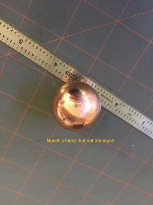
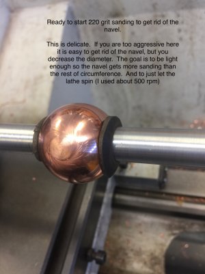
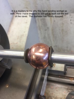
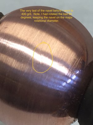
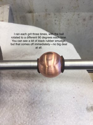
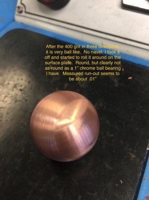
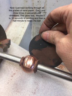
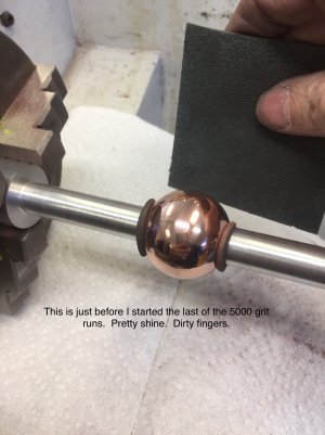
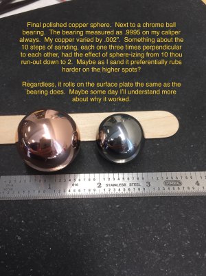
I agree 100%—the swirly pattern is really gorgeous. My sanded-to-polished finish is actually a cover-up. My kludge to sphere-ize the creation navel results in a very different surface finish over the .3” diameter navel. It may actually be nicer to leave with the navel, except one particularly attractive property of a sphere is its complete symmetry. So, to get rid of the asymmetry induced by having the navel, I had to change the surface finish everywhere. So, I pretend that I actually want the polish look. If you can’t have what you want, want what you have. As the swirl pattern is, indeed, spectacular, I may make another and leave the swirl pattern (and the navel). -Bill
 
I just watched another version of how to turn a ball with a boring head but it was on a lathe. It looks a little bit easier than doing it on a milling machine. Here is a link to it.

 
I did wonder if removing that was part of the reason.

It should be possible to make some interesting patterns by doing the first op, popping in the lathe to part, then mounting on a superglue arbor with the pip facing out and doing another pass. Could be pretty cool. Changing the angle would change the overlap in the middle
 
Would love to see that. I'm sure I'm not alone.

Regards,
Terry
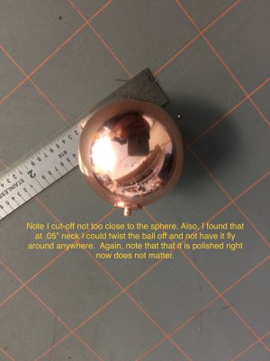
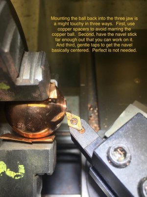
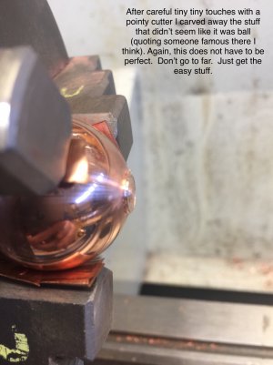
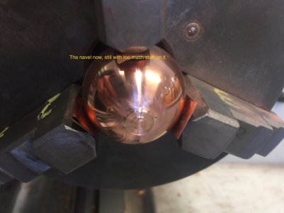
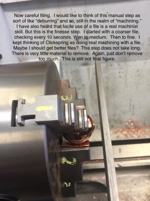
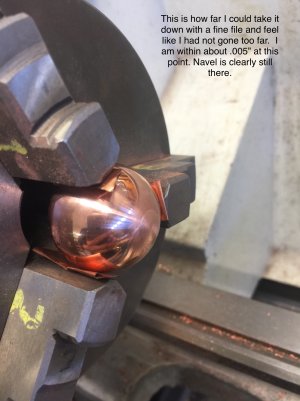
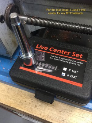
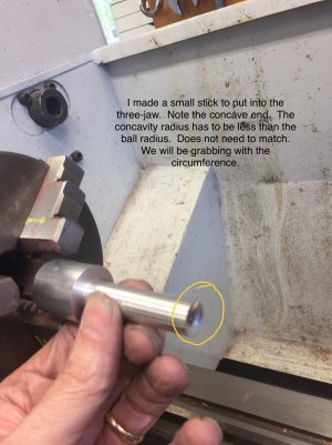
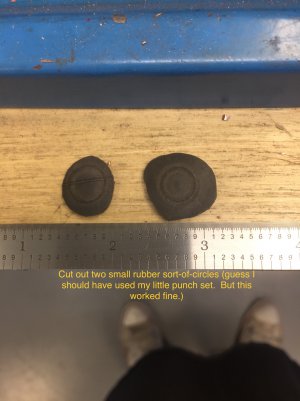
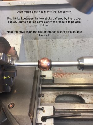
OK. Here is the best explanation I could come up with for how I got rid of the navel. It is a kludge from start to finish. As a beginner I just try stuff. The failures (many) go into a box I call “study pieces.” Now and then, something works. This one worked. But I would love to learn how real machinists machine a (complete) sphere. I will try to past all 24 annotated pictures here. If a single message can’t take so many pictures, I’ll just see what it took, and then post the rest.

-Bill
175BD67D-CB95-4B1F-9C05-945CE5749103.jpeg71CD7FD6-E4CE-4633-8EFD-9431DB4828A2.jpeg9AF3AFF0-E0FA-4E1B-B423-F9ADF628F262.jpeg29A8BA81-60CF-4A12-B937-FDD2D595E5C3.jpegF8E73BFF-F653-4F23-89DA-3EFD29180827.jpeg
 

Attachments

  • EB884E01-15E2-4AE3-A7CB-3C6C0F4246A3.jpeg
    EB884E01-15E2-4AE3-A7CB-3C6C0F4246A3.jpeg
    995 KB · Views: 25
  • 1098B3D0-1F2C-4D97-AB5B-3E85AF0D08CB.jpeg
    1098B3D0-1F2C-4D97-AB5B-3E85AF0D08CB.jpeg
    1.2 MB · Views: 23
  • 05D47649-381F-4DC2-BACD-851E0C3C1ADF.jpeg
    05D47649-381F-4DC2-BACD-851E0C3C1ADF.jpeg
    761.8 KB · Views: 22
  • 7F9065A8-84AE-4C79-A03B-E6C3350CEF91.jpeg
    7F9065A8-84AE-4C79-A03B-E6C3350CEF91.jpeg
    732 KB · Views: 22
  • 46F8846A-E0EE-4E74-85A7-4EBF8854159A.jpeg
    46F8846A-E0EE-4E74-85A7-4EBF8854159A.jpeg
    904.6 KB · Views: 23
  • F0E9D858-1AC0-47DB-8EC6-821A4A892E99.jpeg
    F0E9D858-1AC0-47DB-8EC6-821A4A892E99.jpeg
    813.3 KB · Views: 23
  • DCE15D2C-E5BE-40FC-86B5-55349BB06697.jpeg
    DCE15D2C-E5BE-40FC-86B5-55349BB06697.jpeg
    1,023.8 KB · Views: 24
  • E9A40422-9C93-4255-BF04-A5E92BED7FEB.jpeg
    E9A40422-9C93-4255-BF04-A5E92BED7FEB.jpeg
    1.1 MB · Views: 27
  • 73FBB579-00A4-45E6-8D4E-48380778235E.jpeg
    73FBB579-00A4-45E6-8D4E-48380778235E.jpeg
    991.1 KB · Views: 27
  • 38C4D83A-4F63-4119-B6B4-033C8D5284C8.jpeg
    38C4D83A-4F63-4119-B6B4-033C8D5284C8.jpeg
    854.8 KB · Views: 27
  • 15A69BE9-AF1E-4EAF-87AF-3094D26F5C10.jpeg
    15A69BE9-AF1E-4EAF-87AF-3094D26F5C10.jpeg
    1.1 MB · Views: 28
  • 63BFA199-E842-4D64-B856-1A9892BBFC09.jpeg
    63BFA199-E842-4D64-B856-1A9892BBFC09.jpeg
    767.6 KB · Views: 29
  • C6A85E0D-EB19-451C-BB16-823F80C3C557.jpeg
    C6A85E0D-EB19-451C-BB16-823F80C3C557.jpeg
    718.6 KB · Views: 26
  • B0A50BAF-680E-4810-9870-5CDB2D7B77A8.jpeg
    B0A50BAF-680E-4810-9870-5CDB2D7B77A8.jpeg
    555.1 KB · Views: 26
  • CBF071E5-AEEC-46E0-AD03-4FC767274773.jpeg
    CBF071E5-AEEC-46E0-AD03-4FC767274773.jpeg
    758.5 KB · Views: 26
  • F7FD0A20-308E-4854-819E-30CC3106C0C7.jpeg
    F7FD0A20-308E-4854-819E-30CC3106C0C7.jpeg
    785.4 KB · Views: 27
  • F73A972E-F7D7-4C08-9793-B5E2E0C2D0AF.jpeg
    F73A972E-F7D7-4C08-9793-B5E2E0C2D0AF.jpeg
    774.1 KB · Views: 26
  • CC2EECFF-528D-4747-919F-17A99EA6C8A0.jpeg
    CC2EECFF-528D-4747-919F-17A99EA6C8A0.jpeg
    832.2 KB · Views: 27
  • 9C96C520-640E-4594-A5B1-788E72DE37EC.jpeg
    9C96C520-640E-4594-A5B1-788E72DE37EC.jpeg
    1.1 MB · Views: 26
OK. Here is the best explanation I could come up with for how I got rid of the navel. It is a kludge from start to finish. As a beginner I just try stuff. The failures (many) go into a box I call “study pieces.” Now and then, something works. This one worked. But I would love to learn how real machinists machine a (complete) sphere. I will try to past all 24 annotated pictures here. If a single message can’t take so many pictures, I’ll just see what it took, and then post the rest.

-Bill
View attachment 320490View attachment 320491View attachment 320492View attachment 320493View attachment 320494
Thanks for the excellent write-up. Very impressive work.

Regards,
Terry
 
Interesting, mine didn't come out with the oddly shaped tip. I set up a CAD drawing where I can set the desired sphere and holder radius and it spits out the angle and other measurements for me, which saved a lot of potential calculation errors.

Thanks for the excellent write up.
 
  • Like
Reactions: tjb
...I set up a CAD drawing where I can set the desired sphere and holder radius and it spits out the angle and other measurements...
That is very cool. I do not understand the multiple parameters. I get that I set the cylinder diameter (D) and tab diameter (d). I then set the boring bar sweep diameter to be (a smidge under) the cylinder diameter. I set the the cylinder up-angle so it is horizontal from where the top of the tab touches the cylinder to the middle of the cylinder. I center the mill’s Y on the cylinder. Maybe I am not positioning the X correctly? I position so the boring cutter just touches the center of the end of the cylinder. (Well, as Stefan said, a smidge inside the cylinder of that position. I have the sense that the centrifugal force on the boring cutter expands its diameter a bit. I feel like it is a few thou. But maybe it is more?). I am not really sure how long the cylinder should be. I have guessed it needs to be longer than the diameter. Maybe like 1/(cos(atan(d/D)). But I am not confident this analysis is correct. Other than that tiny axial end knob everything else ends very spherical (well, constant diameter, which is not really the same, but I’ll pretend).

What system do you do the CAD in? Is there a way to post your logical construction process (not simply the drawings)?

-Bill
 
Actually, I can share my OnShape document. All you need is a free account and you can tweak the parameters to suit. No prior knowledge required, just put you numbers in and the drawing will update itself. If anyone is interested, I'll do a little video explanation. Stefan's was great, but he missed some of the basics like setting the cut radius and lining up. I'll get on it :)
 
Maybe I am not positioning the X correctly? I position so the boring cutter just touches the center of the end of the cylinder

Actually, just re-read this. I did the same, then moved X so the cutter was going to be 0.1mm inside. I reckon that's maybe where you might improve the end. It just seemed like the right thing to do, if that makes sense?
 
Actually, just re-read this. I did the same, then moved X so the cutter was going to be 0.1mm inside. I reckon that's maybe where you might improve the end. It just seemed like the right thing to do, if that makes sense?
Yes. I did follow Stefan and moved it a smidge inside. Maybe I need to move it two smidges.
 
Back
Top