[How do I?] Mach 3 Work Offset

TomS

Active User
H-M Supporter Gold Member
Joined
May 20, 2013
Messages
1,906
I've done some reading and ran a simulation in Mach 3 but to be sure before I unnecessarily waste material I thought I would run it past the brain trust. How do I set up work offsets and apply them to my gcode?

My first part is located at X=0, Y=0 and Z=0. Y and Z do not change for subsequent parts. The X axis work offset for the second part is -5.750 and the offset for the third part is -11.500. I've gone to the Offsets screen and clicked on the Save Work Offsets button. In the Work Offsets Table G54 is all zero's, G55 is X = -5.750, Y and Z are zero's, and G56 is X = -11.500 and Y and Z are zero's. I ran the simulation and it appears to be working correctly. G54 runs the first part starting at 0/0/0, G55 runs the second part at X-5.750/0/0 and G56 runs the third part at X-11.500/0/0.

The way I ran the simulation was to run the first part, go to the Offsets screen, select G55, back to the Program Run screen, Regen Toolpath, then run the second part. Then back to the Offsets screen, select G56, back to the Program Run screen, push Regen Toolpath to run the third part. Is there a way to incorporate the three work offsets into my gcode file? I have 48 parts to make so I'd like to eliminate the toggling between screens.

Tom S.
You should be able to enter the offset as G54, G55. G56, etc. as a line in your G code. As I recall, they are modal and so will remain in effect until explicitly changed. Watch your programs, though, if generated with a CAM program as they are often entered into lines of code just to make sure that you are using the correct offset.

In the Tormach flavor of Mach 3, you can enter offset past G59 using G59Pxx where xx is 1 to 255

I gave it a shot and it didn't work. I'm sure it's the way I entered it.

Tom S.
 
The way I normally do multiple parts is to place all of them in the drawing (as copies) and just run the CAM program on all of them. That way I don't have to worry about offsets. I have a drawing of my mill table with the work envelope and I just overlay the parts.

I hope that made sense. :)
 
The way I normally do multiple parts is to place all of them in the drawing (as copies) and just run the CAM program on all of them. That way I don't have to worry about offsets. I have a drawing of my mill table with the work envelope and I just overlay the parts.

I hope that made sense. :)

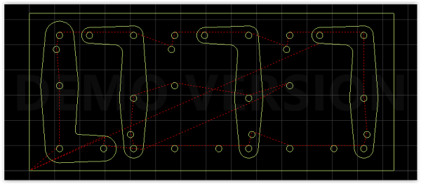
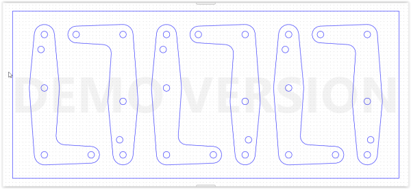
I tried that but when I did cutter offset two of the three parts/objects went away. Actually I have six parts in my drawing but the same thing happens (parts disappear from the screen) when I do cutter offset. I'm trying different work arounds so I can cut parts. I have 48 parts to make and doing them one at a time takes way too long.

Here are a couple of screen shots that may explain it better.

Here's my CAD drawing. Lower left is X0 Y0.
CAD DWG.PNG

Here's my CAM screen shot after I selected the first, third and fifth parts and tool offset.
CAM DWG.PNG


Tom S.
 
That's strange. If I understand correctly, the cam program is ''throwing out'' the parts?
 
What CAM program are you using? I have never seen anything like that happen before.
 
Would you export a DXF file of your drawing and upload it here. I want to try something with AutoCAD. Change the DXF extension to TXT and you can upload it.
 
Back
Top