LMS Mini Lathe Feed Rate - Vary Gears?

Thanks Tom. It appears that the the 4200 link is only an advertising flyer, not a manual.
The link to the 4200 isn't an advertisement. It addresses the upgrades from the base 4100 to the "deluxe" 4200, but is basically a user's manual for the digital readouts on the handwheels that come with the 4200.

Tom
 
The link to the 4200 isn't an advertisement. It addresses the upgrades from the base 4100 to the "deluxe" 4200, but is basically a user's manual for the digital readouts on the handwheels that come with the 4200.

Tom
The LMS 4200 is indeed a physically metric machine, as it was made OUS for an international market and rebranded/modified by different vendors. As they note in the manual:

”There are 40 divisions on the dial. Each turn of the handle advances the compound rest 1 mm or approximately 0.040”. The distance is actually 0.03937”, an error of a little less than 2%.”

The 4200 added the DROs on the manual Cross Feed and Compound Rest and metal feed wheels & gears. Presumably, the error in the manual dials is corrected in the DROs, but I haven’t confirmed that. The machine is currently in transition from a 7x12 to a 7x16 with new Bluetooth Z & Y axis DROs, so I can’t check for a while.

I see the Groups I/O 7x12 group has printable gears, as noted above, but all in the 20-80 ranges of sizes.
 
I see the Groups I/O 7x12 group has printable gears, as noted above, but all in the 20-80 ranges of sizes.
FYI oddball gears are trivial to generate in CAD. If there's a gear you need that isn't among that site's printable gears files, let us know and I or someone else can make a new file. Just need to know DP, PA, # of teeth, bore size, thickness, and keyway dimensions. All of this information except # teeth should be in the files for the printable gears so maybe just post the file closest to the one you want, and include any other desired features like offset, hub, set screw hole, etc.
 
The link to the 4200 isn't an advertisement. It addresses the upgrades from
I am sorry Tom. I did not mean to belittle the links usefulness. I was hurrying and called it an advertisement in error. It just did not help me figure out the gearing and so I moved on quickly.

Dave L.
 
I am sorry Tom. I did not mean to belittle the links usefulness. I was hurrying and called it an advertisement in error. It just did not help me figure out the gearing and so I moved on quickly.

Dave L.
No worries. :encourage:

Tom
 
The LMS 4200 is indeed a physically metric machine, as it was made
Thanks. No power cross feed! It is clear that they put an Imperial, 16TPI, lead screw on the machine. However, this is not uncommon that these are switched from metric to Imperial when sold into the USA.

In fact, the LMS web site for determining TPI, https://littlemachineshop.com/reference/change_gears.php , requires that you specify whether or not you have a lead screw of 16TPI or 1.5mm pitch.

At this same site it also says: "The normal set of change gears includes the following gears: 20, 20, 35, 40, 40, 45, 50, 55, 57, 60, 65, 80, and 80 teeth." Counting these says that there are 10 unique gears but the 20, 40, and 80 are duplicated. However, when I looked at the gearing plate photo that you shared I found 11 unique gears shown. It show a 21T gear in the metric plate. It would appear that the LMS web side has just left the 21 out. In the photo of https://littlemachineshop.com/images/gallery/ds/4200 HiTorque 7x12 Deluxe Mini Lathe.pdf I can count 11 gears.

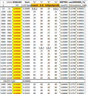
By the way, if it is not obvious, in my spread sheet I refer to the spindle location and the lead screw location as gear axles. In the LMS4200, the "Spindle" column of the lathe sheet would be the LMS4200 lathe's "A" location and the lathe sheet "LeadScrew" column would be LMS4200 lathe "D" Locations. The table or lathe sheet the phrases like "A-A" or "B-B" means the pair of gears on a single axle labeled "A" or "B" while a phrase like "A2Spin" means the gear that is in contact with the gear on the the spread sheets A axle. So the LMS4200 effectively has 3 axles, where the "B" and "C" notations represent the 2 gear locations that are one axle and are turning together.

I added the gears 21 and 57 to the spread sheet and reran the program last evening. Without duplication it found 12,321 gear combinations, not too bad as it only took a while to run. Of course very many of these are not available to you due to the the lack of duplicate gears or combinations which will not physically fit. (I have seen some lathes where the gear combinations and the gear levers yield a lot more combinations and can take a hour or more to create the list.)

I suppose if I knew exactly which gears you have and how many of each one, we could write a macro which would remove the arrangements which are unavailable. I may think about this a bit more. (Do you have 11 gears plus duplicates of the 20, 40 and 80?) Likewise, if one were to come up with rules about which gears do not physically fit these could be found. However, this later endeavor would probably be much more difficult. The former would be a macro that is some what specific to the lathe model.

You can add the gears to the workbook sheet "uwLMS4200_7x" that was posted yesterday and see. Don't forget to put the "Zzz" flag at the end of the column of gear values. The macro watches for this flag. Or, if you like I can re-post the work book with the additional gears.


The Standard Threads table attached as pdf. One can adjust the approximation limits for each thread that was searched and change this table. If you cannot find a gear arrangement that works just adjust the approximation. See sheet tab "uwSrchList." The 21TPI gear improved the number of approximate Metric pitches that could be found. You might have noticed that one can get far more exact metric pitches if he has a gear with 254T, or a sub-multiple of the number . This is the result of 1"=25.4mm. The fact that the lead screw is non-metric causes the need for this gear. However, since 127 = 254/2 it also works. Since 127T is a prime number and the gears must have an integer number of teeth, we can use no smaller value. However, the 21T gear is close. 21*6=126. It is only off by 1/127= 0.79%. Hence, most of the metric Pitch tables provided by the lathe manufactures are not exact, even though they write them out as such! So even though some folks think they need specific gears to generate an exact thread value they are commonly using approximations at the manufacture's recommendations and do not know any better, especially for US lathes the metric pitches.
 

Attachments

Awhile back I wrote a C program that, among other things, determined the number of unique threads that could be cut with the stock set of gears for a 7x lathe. It came to 24,402. The finest was 256TPI, which is the combination used for the "fine" power feed. The coarsest was 1TPI. It is cut using the same set of gears as for the finest, but the gears are swapped around.

One of the reasons I wrote the program was to explore making differential screws. To that end I found that it was theoretically possible to cut threads which would produce 2.367x10^-6" motion/turn. 2.367 micro-inches/turn. The TPIs to do that are 65.00 and 65.01, but, given the sloppy nature of most, if not all, 7x lathes, attempting that would be an exercise in futility.
 
Interesting. I would be interested in seeing it. I am not for sure why you got such a large number if they TPI values only included the unique value, i.e. only one of each. Or do you mean something else by unique? I had thought about writing my workbook in a more basic computer language like C or Python, but decided that it was likely that more HM users could use an Excel program and that after running it one could customize the appearance of tables easier. Python certainly would have been easier than using the macro language. Anyway, I decided I wanted to learn about writing macros.

I still have my old SB-10-K heavy with the extended Norton gear box. I love that gear box it has 10 fundamental threads by 7 2x factors to yield 70 threads for an single set of external gears. 4TPI out to 480TPI. There is no separate feed bar. I purchased it used and never got any exchange gears. I need to rebuild parts of the saddle etc. but it is still useful.
 
Last edited:
@MaverickNH

I was thinking about your desire to have a slower feed rate and the suggestion that you get a 127T gear. You could get two of these 3D printed, then assuming that they will fit, replace the 80/20/80/20 arrangement with 127/20/127/20 and I think this will get you to a TPI value of
645.16 or inverting this a feed rate of 0.00155 inch/turn. The nice thing about this would be that just using one of the 127 gears could also be used at the center position to improve your metric threads.

Just a passing thought. I have a "Prusa i3_MK3S" 3D printer. If you can make a 3D printer CAD STL file for it I would print them for you. I would like to see how well this would work anyway. Prusa even supplies a slicer software to convert from the CAD STL file to the Gcode file. https://www.prusa3d.com/page/prusaslicer_424/

I even think that FreeCAD software will generate 3D gears pretty much automatically from the gear tooth size and number of teeth or diameter info.

Dave
 
Interesting. I would be interested in seeing it. I am not for sure why you got such a large number if they TPI values only included the unique value, i.e. only one of each. Or do you mean something else by unique? I had thought about writing my workbook in a more basic computer language like C or Python, but decided that it was likely that more HM users could use an Excel program and that after running it one could customize the appearance of tables easier. Python certainly would have been easier than using the macro language. Anyway, I decided I wanted to learn about writing macros.

I still have my old SB-10-K heavy with the extended Norton gear box. I love that gear box it has 10 fundamental threads by 7 2x factors to yield 70 threads for an single set of external gears. 4TPI out to 480TPI. There is no separate feed bar. I purchased it used and never got any exchange gears. I need to rebuild parts of the saddle etc. but it is still useful.
I misspoke regarding the number of unique TPI's. The number I indicated actually is the total number of possible combinations of gears, nothing more. No matter if they can actually be realized or not. Apologies for that. The actual number of unique and realizable threads comes to 1500, quite a bit less. In my defense, it's been awhile since I ran any of those old programs.

If you want to examine my code, send me a PM with your email and I will send it to you. Not because of confidentiality reasons, just that it is more related to programming than machining. For instance, I used a hash scheme to simplify the process of quickly distinguishing unique TPI's (and to keep track of how many ways each TPI value could be set up). Much faster and easier than something like an insertion sort.

FYI, 16TPI turned out to be the most-common one, with 116 different gear combinations.
 
Back
Top