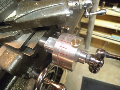
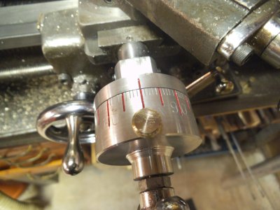
Little Atlas 618 with a BIG cross feed dial.

David S

Active User
H-M Supporter Gold Member
Joined
Nov 18, 2012
Messages
1,352
Hi folks, my name is David. I am from Canada ...eh.

After reading the thread from Bernard (aka Dranreb) about making his larger cross feed dial, I decided it was time to try and do something with the tiny one on my Atlas 618. My objects were:
1 No permanent change / alteration to the 618
2 100% reversible
3 No buying anything.. must be made from shop supplies.
4 Functional.. of course.

Materials at hand: aluminum 6061-T6, free machining brass rod, all sorts of fasteners etc.

So here we go.

The first thing is to extend the dial pointer forward so that the dial can clear the cross slide. With the present 618 the clearance between the bottom of the cross slide and the pointer is around 0.008" on my lathe.

I decided that the ultimate diameter of the dial and pointer dial would be just under 2". So I started with the pointer, making an extension that would slip fit over the existing pointer, and milling a flat so that the cross slide would clear it. See first pic.
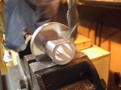
milling fixed dial extension.jpg

I milled it down until the web was about 0.010" and then hand filed the flat so that it would clear the slide. I wanted to keep some material there so that swarf wouldn't get into the lead screw thrust bearing. On the end facing us I drilled and tapped for three set screws, one on either side and one on the bottom.

Next will come the lead screw shaft extension. I am not sure if there is a time out for doing posts, so will break it up.

milling fixed dial extension.jpg
 
Next step is to make the lead screw shaft extension. The original dial pointer boss is 0.75" diameter so I wanted everything to be under that dimension so that final assembly would be easy.

On the original 618 the lead screw end play is adjusted by changing the position of the crank handle with the nuts on either side of the handle. With the extension, the end play will be taken up with the extension hardware.

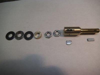
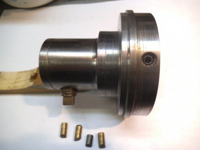
I machined a brass extension with a female thread (5/16-24) to fit the existing shaft and a male 5/16-24 to accommodate the crank handle. The original crank handle is locked for rotation to the shaft by a woodruff keep 1/16" thick.

My first thought was to drill and tap two set screw holes to accommodate two dog nose set screws that would go down and engage the original woodruff key way. My screws were too large in diameter. When I turned them down to 1/16" I was surprised by how soft the screws were....they cut like butter. I figured they wouldn't be robust, so after going thru the work, abandoned that approach.

Next was to mill a 1/16" slot between the two set screw holes that would allow a long key with a radius bottom to fit in the original woodruff key way. Before putting it in, I milled two shallow pockets on either side of the key and notched the key at the top so it could be extracted with two sharp objects.

In order to take up the thrust when the cross slide is being withdrawn, I just happen to find a set of thrust bearings that would be perfect. So after some dry fitting and machining of a spacer to control the end play when it was assembled, here are the pics.

Hardware
shaft extension hardware.jpg


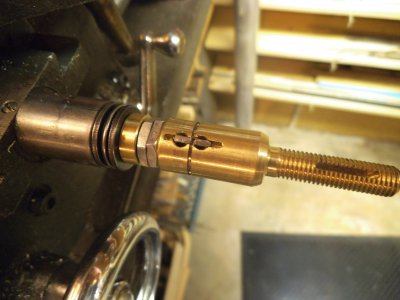
and the complete assembly on the lathe
shaft extension on lead screw.jpg

Next post will be the dial.

shaft extension hardware.jpg shaft extension on lead screw.jpg
 
Making the dial. I won't describe the actual machining..just standard stuff. I had to figure out how to make the graduations....100 in all.

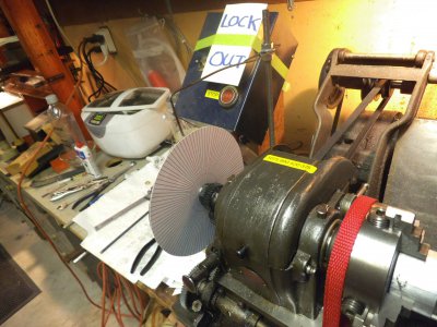
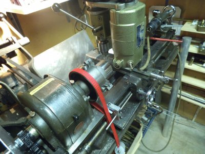
First was to make an index wheel. Using Viso mechanical design I made a index wheel with 100 graduations, every 3.6deg apart. I color coded the graduations. Red for the 10s, green for the 5s and black for the thous. Printed in in hi res on glossy photo paper and mounted it to a thin aluminum disc with double sided tape. Fortunately for once I thought ahead a bit and before I set up to machine the actual dial I installed a collet in my spindle and snugged it up with the draw bar. Now I could remove the draw bar and use it to lock the index to the back of the head stock spindle. To make the graduations I decided to engrave them. Installed the headstock and milling column from my Unimat lathe onto the cross slide of the 618, centered it and locked it down by tightening a gib screw on the cross slide.

I don't have a way to lock the atlas chuck from rotation. I used sort of a prony brake with a piece of webbing, fixed to the bed, wrapped around the chuck with about a three pound mass on the free end, and always turning the chuck backwards to index.

Graduations were down in three passes / rotations. First for the 10s cut in to about 1/2" set the carriage stop and did the remainder, then moved into about .3" for the 5s, and finally the thous.

All is good so far. By the time I was done...well I was just glad to be done. Tore the set up all down, and then said "damn" I forgot to mill flats under the 10s so I could use numeric marking punches to mark the major graduations. Ended up trying to punch them on the round and didn't do so good on some.. so not going to show that....embarrassed.

Index set up
indexing dial on lathe.jpg

Unimat mounted on cross slide for engraving

Unimat head on cross slide.jpg

At the zero mark I used a thumb screw to lock the dial to the shaft. It is drilled all the way through with a #36 drill bit and then the dial is reversed and a #25 drill is drill back to just inside the collar below the locking screw, so that an intermediate piece of brass is installed to do the locking on the shaft to prevent galling.

To make it more readable for my ol eyes I put nail polish in the 10s and 5s graduations.

Finals here

finished dial side view.jpg

Finished dial close.jpg


David

indexing dial on lathe.jpg Unimat head on cross slide.jpg finished dial side view.jpg Finished dial close.jpg
 
Nice work David, very stylish and I like the way you got around the woodruff key issue...Did you fit a snap ring to hold it in place?

I see I'm not the only one to worry my machine starting by mistake..

I've fitted roller thrust bearings to mine now, pics to come, bigger dials certainly make life easier don't they!

Bernard

Bernard I was going to use a ring to hold it in place.. you can see the groove.. but the inner bore of the dial keeps everything in, so not necessary.

and thank you for the comments.

David

- - - Updated - - -

Great job! I see you mentioned that you wanted it to be a 2" diameter, did you use 2" rod or larger and turn it down and is it 2" when finished? Sorry for the questions, I am new to machining and interested in modding my machine like this. Thanks for posting!

Hi. The rod that I had was nominal OD 2" as a mill finish. I turned it down to about 1.980" if I recall.

David
 
David,

Very nice work! This is on my list of projects for my Logan lathe. Ca you post a pic of how you mounted your Unimat to the cross slide? This is something I've considered as well.

Steve
 
David,

Very nice work! This is on my list of projects for my Logan lathe. Ca you post a pic of how you mounted your Unimat to the cross slide? This is something I've considered as well.

Steve

Steve Thank you. I don't have a picture of it on the lathe right now, but I do have a picture of the adapter. For size it is 2.75" diameter where it mounts on the cross slide and overall height is about 2.7". Essentially you remove the compound and place this on the cross slide in its place, and tighten down 4 set screws around the periphery just like the compound except more screws. And there are 4 tapered brass pieces in the set screw holes. The top is bored to accept the unimat column and a cross screw to secure it. I made this years ago..

Hope this helps.

David
Unimat mount.jpg

Unimat mount.jpg
 
David,

Yes,that answers my question. Thank you!

I couldn't tell from the previous picture whether you were using the Uni column or some other type of bracket.

Thanks again.

Steve
 
Making the dial. I won't describe the actual machining..just standard stuff. I had to figure out how to make the graduations....100 in all.

First was to make an index wheel. Using Viso mechanical design I made a index wheel with 100 graduations, every 3.6deg apart. I color coded the graduations. Red for the 10s, green for the 5s and black for the thous. Printed in in hi res on glossy photo paper and mounted it to a thin aluminum disc with double sided tape. Fortunately for once I thought ahead a bit and before I set up to machine the actual dial I installed a collet in my spindle and snugged it up with the draw bar. Now I could remove the draw bar and use it to lock the index to the back of the head stock spindle. To make the graduations I decided to engrave them. Installed the headstock and milling column from my Unimat lathe onto the cross slide of the 618, centered it and locked it down by tightening a gib screw on the cross slide.

I don't have a way to lock the atlas chuck from rotation. I used sort of a prony brake with a piece of webbing, fixed to the bed, wrapped around the chuck with about a three pound mass on the free end, and always turning the chuck backwards to index.

Graduations were down in three passes / rotations. First for the 10s cut in to about 1/2" set the carriage stop and did the remainder, then moved into about .3" for the 5s, and finally the thous.

All is good so far. By the time I was done...well I was just glad to be done. Tore the set up all down, and then said "damn" I forgot to mill flats under the 10s so I could use numeric marking punches to mark the major graduations. Ended up trying to punch them on the round and didn't do so good on some.. so not going to show that....embarrassed.

Index set up
View attachment 67134

Unimat mounted on cross slide for engraving

View attachment 67135

At the zero mark I used a thumb screw to lock the dial to the shaft. It is drilled all the way through with a #36 drill bit and then the dial is reversed and a #25 drill is drill back to just inside the collar below the locking screw, so that an intermediate piece of brass is installed to do the locking on the shaft to prevent galling.

To make it more readable for my ol eyes I put nail polish in the 10s and 5s graduations.

Finals here

View attachment 67136

View attachment 67137


David

Next step is to make the lead screw shaft extension. The original dial pointer boss is 0.75" diameter so I wanted everything to be under that dimension so that final assembly would be easy.

On the original 618 the lead screw end play is adjusted by changing the position of the crank handle with the nuts on either side of the handle. With the extension, the end play will be taken up with the extension hardware.

I machined a brass extension with a female thread (5/16-24) to fit the existing shaft and a male 5/16-24 to accommodate the crank handle. The original crank handle is locked for rotation to the shaft by a woodruff keep 1/16" thick.

My first thought was to drill and tap two set screw holes to accommodate two dog nose set screws that would go down and engage the original woodruff key way. My screws were too large in diameter. When I turned them down to 1/16" I was surprised by how soft the screws were....they cut like butter. I figured they wouldn't be robust, so after going thru the work, abandoned that approach.

Next was to mill a 1/16" slot between the two set screw holes that would allow a long key with a radius bottom to fit in the original woodruff key way. Before putting it in, I milled two shallow pockets on either side of the key and notched the key at the top so it could be extracted with two sharp objects.

In order to take up the thrust when the cross slide is being withdrawn, I just happen to find a set of thrust bearings that would be perfect. So after some dry fitting and machining of a spacer to control the end play when it was assembled, here are the pics.

Hardware
View attachment 67131


and the complete assembly on the lathe
View attachment 67132

Next post will be the dial.


Wow I love it! Great write up and pics! Thanks man!

Bernie
 
Wow I love it! Great write up and pics! Thanks man!

Bernie

Thanks Bernie. I have been lurking here for awhile and figured out that we can't have much of a forum if people don't contribute, so this is my first real post. Just trying to give back for all the advice I get from others.

David
 
Back
Top