Lets talk Workholding and milling sheet goods


I would buy 5/8 X 2 1/4 bar stock, cut the blanks .40-.45 long, clamp in a vise. Use a 3/8 end mill and cut the part profile down .26 deep then turn the part over in the vice and face off the excess.

Kevin
[/QUOTE]

That's what I ended up doing (actually, was 1/2"x3.5" flat bar that I sliced up). It works well, but its a lot of extra time and material wasted. They did turn out well though.

- - - Updated - - -

Stand a piece of bar up in the vise, mill the cross-section into the end, and then saw off the part? If you have a slitting saw it's one setup, one tool change for as many parts as you have usable length on your cutter.

I have conteplated trying this, I am a little gun-shy about slitting saws, but for pieces like this one, where they could basically made as slices of an extrusion, it makes sense. I think I need a real slitting saw, all I have are slotting saws, and they tend to be pretty finicky about binding.
 
On that part, I would clamp it on the top (of the drawing) then run the bottom profile and the ends. Then clamp the bottom, leaving room for the cutter, and run the top profile. I wouldn't try to hold that part in a vice, I would clamp it down to a plate that is bolted to the table. Bolt holes in the backing plate that backup the work when the bolts are screwed in would give more stability as would a couple of properly placed dowel pins. I don't think Gorilla tape by it's self would hold that part, the surface area is too small to take the lateral load.

EDIT:

Another way would be to do the top profile while in a long piece of the material, there you have a lot of clamping area. Then cut the part off and insert it into the cavity fixture that you pre-made. That way the part is well supported, and you only have to clamp it down with a couple of bolts. The cavity depth would be about 0.240 deep to allow some clamp surface. I would start out with bar stock of the nominal thickness, in this case 0.250
 
Last edited:
I have re-read your second comment a couple times, but I don't think I get what you are saying. Do you mean cut the concave portion of the part, then remove from the parent stock (IE, bandsaw), then mate that with a fixture of the opposite shape and clamp to machine the second side.

I need to see if my cam software will do that, it's pretty particular about things, but I could see that working. Probably more work than I want to do for a single part, but for doing a bunch, it could be worthwhile.

I recently made a small fixture plate similar to OxTools and his "mini pallet". It's about 4x6". I have a larger piece of cast plate set aside for a larger version, and wondering if others suggestions of integrating fixturing holes into non-critical areas is the way to go. I don't think it would work for the example part I gave, but for larger flat parts, it could be ideal. I think I may also need to expand my clamp selection, I just have a set strap clamps.

I'd like to keep this thread going as long as I can. To me, this is the most challenging part of CNC (and machining in general), IE, how do I hold this part? Ideally it happens in as few steps as possible, with as little waste as possible, though how to do that is not always obvious up front.
 
I have re-read your second comment a couple times, but I don't think I get what you are saying. Do you mean cut the concave portion of the part, then remove from the parent stock (IE, bandsaw), then mate that with a fixture of the opposite shape and clamp to machine the second side.


Yes. I would make 2 different profiles in the CAM software. What CAM software are you using? In addition you would would have to make a mirror image profile for the fixture. You already know where the fixture is at because you just milled it out, so you know where it is relative to 0. As far as clamping goes, in this case just a couple of button head cap screws would work, maybe 1/4-20. I probably use bolts more that I use my clamp set.

Sometimes even for one part I fixture it, it just depends what I have to do, sometimes there is no other way. I agree that half of the job is figuring out how to hang on the to work, especially in CNC work. I do all of the machining on the job in my head first, step by step, before I ever make a chip. I do this while sitting at my computer before I go out to the shop to make the part.
 
One trick I learned from our CNC guy in our prototyp shop is to use a low temperature alloy like Cerrobend to hold parts while machining off the back. He start with thicker stock, machine out the profile and then fill the cavity with Cerrobend, which melts at about 160 F. then you flip the thing over, face off the back and melt the Cerrobend for the next part.
 
VacBase.jpgVacuumPort.jpg
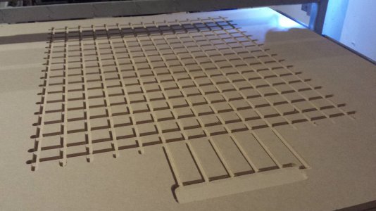
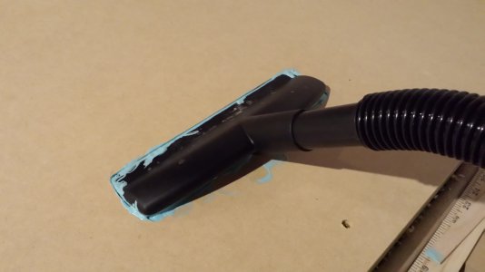
This was my first attempt at a vacuum jig. I used two sheets of 3/4 in. MDF. The vacuum base was a series of slots (bottom sheet)and a pocket for the vacuum port (top sheet). Flexible 'goop' to seal the port, as air leaks remove quite a bit of holding power. The top sheet of MDF contained the vacuum port. I drilled a matrix of holes (positioned over the slots) where I wanted the hold-down to be. I used Cambam to generate both the drawing and the g-code and the drill matrix. I used a 6 HP shopvac from Lowes, (smaller hose diameter type) for suction.
Results: It held the sheet well for outside cuts using larger pieces of material. For little parts, will probably have to build a jig to cover up the unused "sucking" holes in the top piece.

Issues: This approach used up 1 1/2 inches of my 4 inch Z height. MDF is somewhat porous, so there might be some unintended leakage. I have not tried this jig with aggressive cuts on plywood, just plastic so far.

Plans: Rebuild the jig using plywood (sealed with a light varnish) so that the vacuum base becomes the bottom structural base of the router. The top vacuum port sheet will be used as the sacrificial Spoil board. This dual use of structural elements should fix the z height problem and give more work holding options.

VacuumPort.jpg VacBase.jpg
 
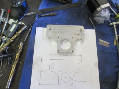
A bit more on work holding. Here is an example of one way to hold this stepper motor mount for machining.

This is the part
IMG_0225.jpg

I didn't have an extra piece of aluminum to put under the work, so I used a piece of MDF bolted to the table with 1/2 flat head cap screws.
I pre-positioned t-nuts under the extra holes, then I screwed a stud into one of the t-nuts, centered on it and set the position in the DRO. This is the center of the big hole, and is centered on the middle t-slot. Eyeball close is good enough for this operation.

The MDF was a piece that I had used for something else so it already had the 1/2 inch counter sunk holes in it.
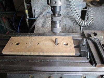
IMG_0214.jpg

Next I drilled & tapped two 1/4-20 holes in the MDF where the center of the slots will be.
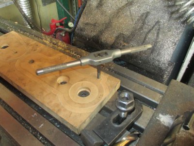
IMG_0216.jpg

Then I positioned the work piece and drilled a 1/2 inch hole in the middle of the big hole area and bolted it down to the t-nut. In this case, the exact location of this hole on the plate is not critical, as long as there is enough material around it to make the part. All of the other dimensions are then relative to this location.
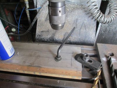
IMG_0215.jpg

Then I drilled the two 1/4 inch holes and screwed those into the MDF. This is strong enough to keep the work from rotating around the 1/2 bolt. The i/2 bolt is actually doing most of the holding.

The other three 1/4 holes are where the cutter is going to plunge in the next operations. One hole above each 1/4 screw, and one in the upper right corner.

I needed to work back from the end a bit because of some holes on the other side of the plate, so I also had room to put a clamp there, out side of the part.
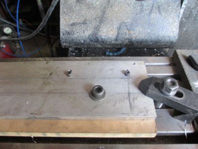
IMG_0217.jpg

I also clamped the other end of the bar, but it didn't really need to be clamped.
View attachment 80712


The part is now roughed out. I used a 1/2 inch, HHS, TIN coated, 3 flute, aluminum cutting, rougher. full width cut, 0.125 DOC, 2200 RPM, 10 IPM, WD-40/Kerosene spray mist coolant.
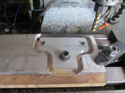
IMG_0220.jpg

The finish cut. 1/2 inch, HHS, TIN coated, 2 flute, aluminum cutting, finishing. 0.015 cut, 0.500 deep, 2600 RPM, 10 IPM
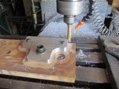
IMG_0221.jpg

Cutting the 5/16 slots. I removed the two 1/4-20 bolts and installed the clamps. I already had a t-nut positioned under a hole in the MDF for the left clamp. The clamps are just barely grabbing the edge of the work to get tool clearance, just to insure it doesn't slide sideways. 1/4 inch, solid carbide, 2 flute, router bit. 3450 RPM, .125 DOC, 10 IPM
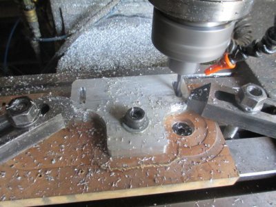
IMG_0222.jpg

Once the slots were done, I re-positioned the clamps to get more bite on the work, then removed the 1/2 bolt. Note that the clamps are not positioned symmetrically, I needed clearance for the tool path on the next operation.
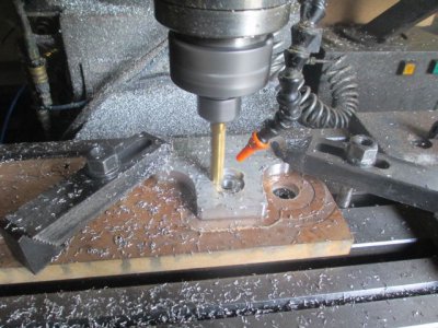
IMG_0223.jpg

The next operation was drilling and tapping holes, I didn't have to move anything.
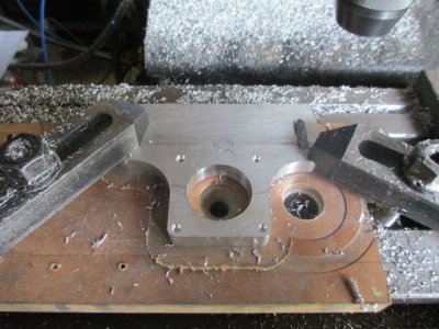
IMG_0224.jpg

Every operation I did here was pre-planned before I made a chip. I hope this helps someone else think through a setup and machining operation.

IMG_0214.jpg IMG_0215.jpg IMG_0216.jpg IMG_0217.jpg IMG_0218.jpg IMG_0220.jpg IMG_0221.jpg IMG_0222.jpg IMG_0223.jpg IMG_0224.jpg IMG_0225.jpg
 
Excellent, thanks for that Jim.

The question that comes to my mind is, how you you do it differently if you had to make four of those parts? What about a dozen? Also, any problems with pullout on the threads in MDF?

I have used MDF as a sacrificial surface before, but haven't threaded into it. I have also had problems with coolant (even mist coolant) causing it to expand a bit, so I have not always gotten more than one use out of it.

I haven't had any pullout problems in the MDF, but in this case I didn't tighten the screws that tight, just snug. Their purpose is to prevent rotational movement around the 1/2 bolt. Many times I use deck screws to hold parts down. Another option is to use an insert or a wood t-nut. That would give you a very solid metal thread in the MDF. If I am doing a lot of parts on an aluminum fixture where I am continuously removing and installing bolts, I put in a Heli-coil or other insert to get the life I need for the job.

If I had to do more than 1 or 2, I would start with an aluminum backing plate rather than MDF. That particular piece of MDF backed the parts that you see the outline of in one of the pictures. It was hit with the spray mist on that run also, didn't seem to hurt it.

If I had to do a dozen or so, I might set up 2 fixtures on common backing plate. One to do the outside profile, and the other to do the slots and the big hole. Once the slots were cut, then you could use them to bolt the work down to the fixture. The 1/2 hole could be used to bolt the part down while cutting the slots, that and a couple of strategically placed dowel pins.. I would fixture for the outside profile the same way I did it here, using 3 bolts, and rig up a toggle clamp for holding the work while drilling the holes.
 
There is an exterior grade MDF called Exteria that is made from hardwood and resin. Comes in 1/2", 3/4" and 1" thicknesses. Holds up extremely well to coolant and cutting fluids.

For using MDF as a fixture plate for multiple parts I have installed threaded inserts into the MDF.

Jay
 
Back
Top